

Introduction
Spring-loaded connectors—better known as pogo pins—have quietly become the unsung heroes of modern electronics. In 2025, as smart devices grow thinner, more powerful, and more modular, engineers lean on CFE-CONN pogo pins to solve three stubborn problems: dependable contact in ultra-tight spaces, rapid blind-mate docking, and long-life durability under constant motion. From wearables and AR headsets to robotics and EV accessories, pogo pins now anchor power, data, and sensing in ways that traditional fixed connectors struggle to match.
In this guide, we break down seven game-changing uses of CFE-CONN pogo pins that product teams are shipping this year—complete with practical design notes, selection tips, and reliability best practices.
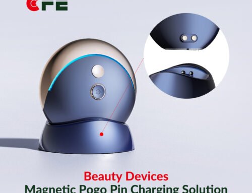
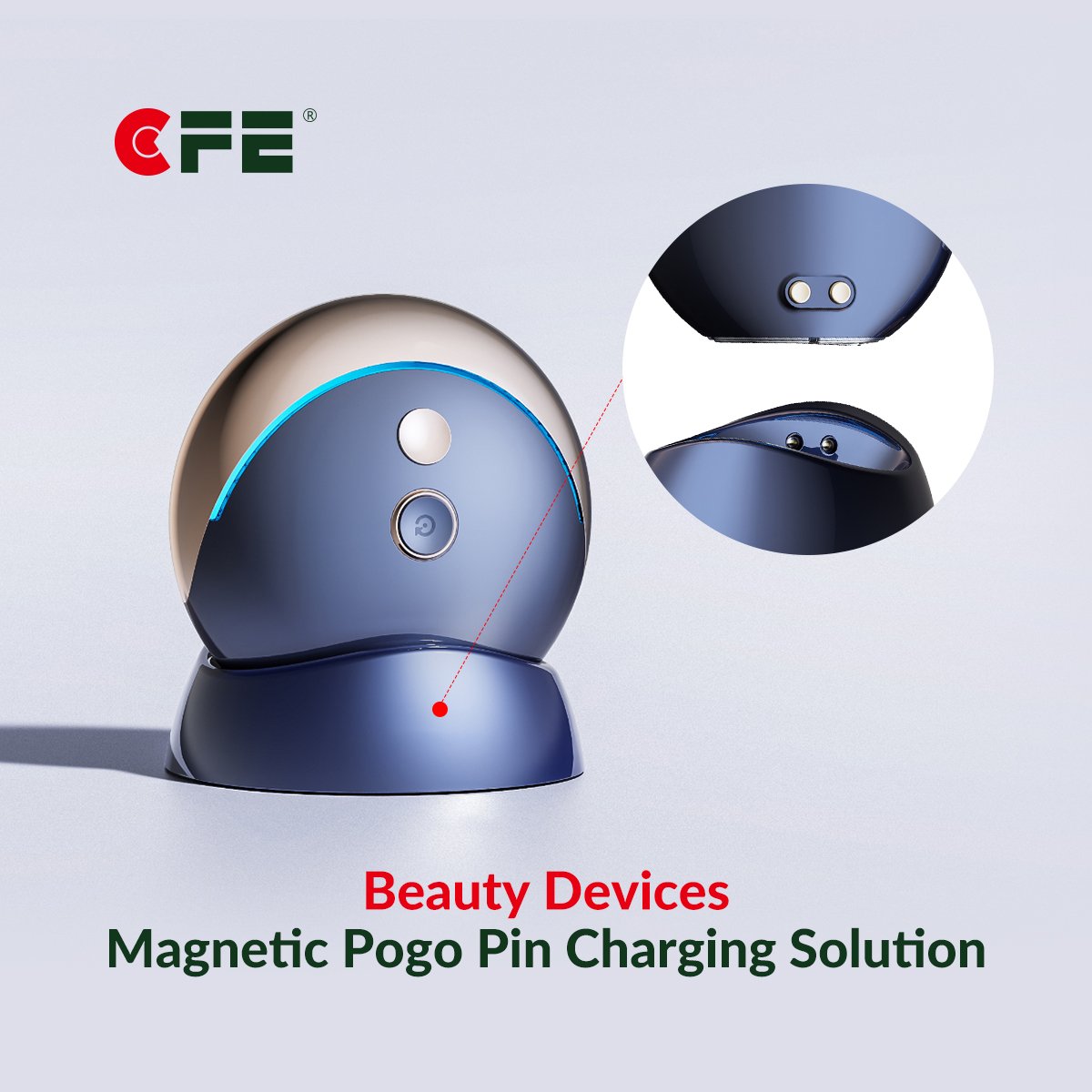
Fast, Safe, and Compact Charging for Wearables
Wearables demand tiny connectors that survive sweat, dust, and thousands of cycles. CFE-CONN pogo pins offer:
-
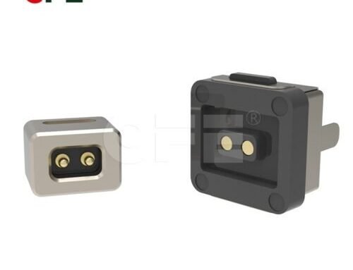
Blind-mate docking: Magnetic cradles snap into place; pins self-align and compress for robust contact.
-
Optimized spring force: Enough pressure to maintain low contact resistance without bruising pads.
-
Corrosion-resistant plating: Gold (Au) over nickel prevents oxidation and keeps charging consistent.
Design tip: For 3–5 V, target contact resistance in the tens of milliohms and validate with a 5,000–10,000 cycle test. Add drainage channels in the cradle to reduce moisture pooling.
High-Integrity Data Transfer in Compact Housings
Whether it’s health metrics from a smartwatch or high-speed logs from a handheld scanner, pogo pins can be tuned for signal integrity:
-
Coaxial or shielded pin variants mitigate crosstalk.
-
Matched lengths and controlled spring travel reduce skew between lines.
-
Ground guard pins placed between data pins further improve EMI performance.
Design tip: For differential pairs (e.g., USB 2.0/HS or custom UART), place ground pins flanking the pair and keep trace stubs short to the landing pads.
Rugged Test Pads and Manufacturing Interfaces
Production success hinges on reliable testing. CFE-CONN’s probe-style pogo pins excel as bed-of-nails or fixture interfaces:
-
High cycle life for repeated ICT/functional testing.
-
Custom tips (crown, flat, concave) to pierce oxides or mate on gold pads.
-
Quickly swap housings so lines can be reconfigured without PCB respins.
Design tip: For stable readings, standardize pad size/finish (ENIG or hard gold), and specify a wipe distance (lateral micro-movement) to self-clean contact surfaces.
Modular Add-Ons for Phones, Tablets, and Handhelds
Magnetic backplates, battery grips, or barcode modules rely on low-profile pogo arrays:
-
Hot-swappable accessories: add power and data without opening the device.
-
Mechanical tolerance forgiveness thanks to spring travel.
-
Sleek industrial design: arrays disappear behind decorative covers when not in use.
Design tip: Use keying geometry (asymmetric pin counts or offset pins) to prevent reverse mating. Include two staggered ground pins to make contact first for ESD control.
Smart Home and IoT Docking Stations
Hubs, cameras, and doorbells benefit from tool-less installation:
-
Weather-resistant pins connect power and Ethernet-over-power or serial data in a single snap.
-
Serviceability: devices lift off the plate without stressing solder joints or cables.
-
Safety: recessed pins and magnetic alignment reduce mis-dock arcing.
Design tip: For outdoor gear, specify IP-minded housings and hydrophobic venting. Consider tapered pin guides to shed water and reduce contamination ingress.
Battery Swaps and Pack Telemetry
Robotics, portable medical gear, and enterprise scanners increasingly use hot-swap battery packs:
-
High-current pins carry charge/discharge, while smaller telemetry pins handle fuel gauge, temperature, and authentication.
-
Staged pin lengths sequence ground first, then data, then power.
-
Reduced downtime: swaps take seconds, extending device availability.
Design tip: Validate current density under worst-case compression; parallel multiple power pins to manage heat rise and ensure even wear across the array.
AR/VR Headsets and Smart Glasses: Lightweight, Low-Profile Links
In spatial computing, every gram counts. CFE-CONN micro pogo pins provide:
-
Sub-millimeter stack heights for temple/bridge electronics.
-
Flexible interconnects between lens modules, sensor boards, and battery arms.
-
Quiet mechanics: minimal rattle compared to sliding or latch-heavy plugs.
Design tip: For head-mounted displays, target vibration-resistant retention features—micro-bosses or magnets—so pins remain at optimal compression during motion.
How to Choose the Right CFE-CONN Pogo Pin
-
Electrical Requirements
-
Current rating (steady vs. peak)
-
Contact resistance at nominal compression
-
Signal bandwidth and shielding needs
-
-
Mechanical Parameters
-
Travel (working vs. max)
-
Spring force (initial and at working height)
-
Tip style: dome (gentle), crown (oxide-piercing), concave (ball contact)
-
-
Environmental Factors
-
Plating: Au over Ni for corrosion; thicker Au for harsh conditions
-
IP exposure: dust, sweat, salt fog, cleaning agents
-
Shock/vibration in wearables and mobile gear
-
-
Integration & Serviceability
-
Blind-mate features, magnetic alignment, keying
-
Replaceable modules in test fixtures or consumer docks
-
-
Reliability & Compliance
-
Cycle life validation (≥10k cycles for consumer, ≥50k for fixtures)
-
ESD handling, creepage/clearance, safety labeling
-
Best Practices for Pogo-Pin Success
-
Design for wipe: A slight lateral motion scrubs oxides and lowers resistance.
-
Use ground-first sequencing: Staggered lengths or stepped pads tame inrush and ESD.
-
Keep pads clean: Specify ENIG and avoid solder mask slivers that trap flux.
-
Parallel power pins: Share load to reduce heating and extend life.
-
Plan for contamination: Add drain paths, shields, and easy-clean access in docks.
-
Document compression window: Define min/nominal/max to guard against tolerance stack-ups.
Real-World Example Stackups (At a Glance)
-
Wearables charger: 2× power (parallel), 2× ground (staggered), 2× data/ID, dome tips, Au plating.
-
IoT camera dock: 3× power, 3× ground, 2× UART, 1× reset, crown tips for weathered pads, conformal-coated board.
-
AR headset bridge: 4× high-speed differential lines with ground guards, shield can over the array, matched pin length.
FAQs
Q1: How many mating cycles can CFE-CONN pogo pins handle?
A: Typical consumer applications validate 10k–20k cycles; test fixtures often exceed 50k+ with appropriate plating and force specs.
Q2: Can pogo pins carry fast data?
A: Yes. With layout discipline—ground guards, matched lengths, and shielded variants—pogo pins support common high-speed protocols used in compact devices.
Q3: What plating is best for outdoor or sweaty environments?
A: Gold over nickel is the standard. For harsher use, specify thicker gold and consider hydrophobic housings and seals.
Q4: Do they support hot-swap batteries?
A: Absolutely. Use staged pin lengths for safe sequencing, multiple parallel power pins, and telemetry lines for pack health.
Q5: How do I prevent mis-mating or reverse docking?
A: Mechanical keying, asymmetrical pin counts, magnet polarity, and recessed guides ensure correct orientation every time.
Conclusion
From fast wearable charging to modular accessories, rugged testing, AR headsets, and hot-swap batteries, CFE-CONN pogo pins underpin the reliability and user experience of 2025’s smartest devices. Their unique blend of blind-mate convenience, compact size, and long-life durability makes them a go-to choice for product teams aiming to ship sleek, serviceable hardware without compromising on power or data integrity. Specify the right force, travel, plating, and array geometry—and pogo pins will quietly keep your next-gen device clicking.
