A connector can pass every electrical test in the lab and still fail in the field because of a ring of rubber that costs a few cents. Connector housing seals are rarely the headline feature of a design review, yet they decide whether a product earns its waterproof claim or collects warranty returns.
This guide is written for OEM engineers and the buyers who work alongside them. It covers how to set an ingress target, choose between seal types, pick materials, size the groove, and validate the result, with specific notes for pogo pin and magnetic connector designs.
A connector housing seal is a compliant barrier, such as an O-ring, gasket, overmold or potting compound, that closes every leak path between the connector housing, its mating half, the cable and the panel, so water, dust and fluids cannot reach the contacts. Reliable sealing depends on three things working together: the right seal type, a compatible material, and a groove and housing geometry that holds the correct compression for the life of the product.
What a Connector Housing Seal Really Has to Do
Think of the seal as one component doing four jobs at once. It blocks water and dust. It keeps doing that after thousands of temperature swings and mating cycles. It absorbs the tolerance stack-up between two plastic parts that never fit identically. And it manages all of this without making the connector so stiff that a user cannot mate it, or a magnet cannot pull it home.
Field leaks rarely come straight through the seal. They travel around it. Almost every failure traces back to one of four paths: the interface between the mating halves, the cable exit, the joint where the housing meets the panel or PCB, and the bores that hold the contacts. A sound design maps all four paths on paper before anyone picks a material.
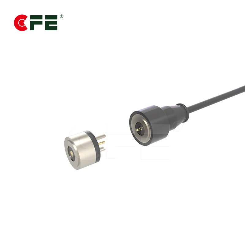
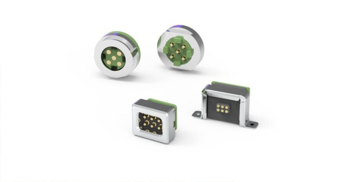
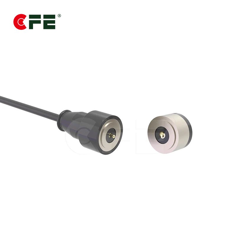
That mapping is also where contact design and sealing meet. The contact surface, whether a spring-loaded pin or a magnetic charging pad, is precisely what you are protecting, and part of it must stay exposed to make a connection. Our waterproof pogo pin range and 5A to 30A magnetic connectors were developed around exactly that tension. The seal does not live apart from the contact. They are designed together or they are not designed well.

Set the Ingress Target Before You Pick a Seal
Start with the environment, then write the rating. IP codes are defined in IEC 60529, and the standard exists to replace vague words like “waterproof” with something testable. The first digit covers solids, the second covers liquids. A fuller breakdown is available in this IEC 60529 explainer.
Over-specifying is as costly as under-specifying. Chasing a continuous-immersion rating for a handheld device that only meets splashes adds tooling, assembly force and test time for no customer benefit. Here is how the common targets translate into sealing work:
| Target | What it means | Typical use | Sealing implication |
|---|---|---|---|
| IP54 | Dust-protected, splash-resistant | Indoor equipment, kiosks | Basic gasket or tight housing fit |
| IP65 | Dust-tight, low-pressure water jets | Smart home, outdoor sensors | Compressed gasket or O-ring at each joint |
| IP67 | Dust-tight, temporary immersion (up to 1 m for 30 minutes) | Wearables, handheld tools | Closed seal path, sealed cable exit, controlled compression |
| IP68 | Dust-tight, continuous immersion under agreed conditions | Marine, underwater devices | Redundant seals, overmold or potting |
| IP69K | High-pressure, high-temperature wash-down (defined in ISO 20653) | Vehicles, food processing | Robust overmold, chemically resistant elastomers |
One caution on IP68: the standard leaves depth and duration to agreement between manufacturer and customer. Two products can both claim IP68 and mean very different things, so always request the test conditions in writing.
Seal Types Compared: O-Ring, Gasket, Overmold and Potting
No single seal wins everywhere. The right choice depends on joint geometry, mating frequency, assembly volume and how much space you can give up. Most robust designs combine two methods, for example an O-ring at the mating face and potting at the cable end.
| Seal type | Best for | Strengths | Watch-outs |
|---|---|---|---|
| O-ring | Round or oval joints, repeated mating | Low cost, proven, easy to source | Needs a precise groove; can twist or pinch during assembly |
| Flat or die-cut gasket | Panel mounts, rectangular housings | Thin profile, simple assembly | Sensitive to flatness and screw spacing |
| Molded or overmolded seal | Complex shapes, high volume | Fewer parts, repeatable sealing geometry | Higher tooling cost, material bonding must be validated |
| Potting or encapsulation | Cable exits, rear cavities | Seals around many wires at once | Rework is difficult; thermal expansion must be considered |
For connectors that mate often, such as charging interfaces, favor a seal that sees compression but little sliding. A seal that drags across a surface on every mating wears out long before the housing does. Static face seals tend to outlast sliding radial seals in these roles.
If your design pairs a connector with a cable, treat the cable exit as its own sealing problem. Strain relief, grommet fit and conductor size all matter, and our guide to AWG versus mm² cable for 5A to 30A magnetic connectors helps match the cable to the grommet before tooling is cut.

Material Choices That Survive the Real Environment
Elastomer selection is where many seals quietly fail. A compound that works at room temperature can harden in a freezer, swell in oil or crack under sunlight. List every fluid, temperature extreme and cleaning agent the product will meet, then match the compound to that list.
| Material | Typical temperature range | Good at | Weak at |
|---|---|---|---|
| Silicone (VMQ) | About -55 to 200 °C | Wide temperature range, flexibility, low compression set | Fuels and oils; lower tear strength |
| Fluoroelastomer (FKM) | About -20 to 200 °C | Fuels, oils, chemicals | Cold flexibility; higher cost |
| EPDM | About -50 to 150 °C | Water, steam, weathering | Petroleum oils |
| Nitrile (NBR) | About -30 to 100 °C | Oils and fuels at modest cost | Ozone, sunlight, heat |
These ranges are typical, not guaranteed. Always confirm against the specific compound datasheet. Pay attention to compression set, the permanent flattening a seal suffers after long compression. A compound with poor compression set may pass a day-one leak test and fail after months in the field.
The hard plastics around the seal matter too. Creep or warpage in the housing relaxes compression just as surely as a tired elastomer. Our article on pogo pin housing materials, LCP versus high-temperature PA explains how housing resin choice affects dimensional stability around sealing surfaces.

Gland and Housing Design Rules That Prevent Leaks
A good seal in a bad groove is still a bad seal. These starting points are widely used for static elastomer seals. Treat them as a first draft and confirm them with your seal supplier’s design guide.
- Compression window. Static face seals commonly work with roughly 15 to 30 percent compression. Too little leaks. Too much speeds up compression set and raises mating force.
- Groove fill. Leave room for the rubber to expand with heat. Keeping the groove fill below roughly 85 to 90 percent is a common rule of thumb.
- Edges and lead-ins. Break sharp corners and add a lead-in chamfer so the seal is never nicked during assembly.
- Parting lines and flash. Keep mold parting lines and flash off the sealing surface. A hairline ridge can be enough to start a leak path.
- Surface finish and flatness. Sealing faces should be smooth and flat enough that the seal contacts evenly around its full perimeter.
- Tolerance stack-up. Run the worst case in both directions. Minimum compression at maximum gap must still seal, and maximum compression must not crush the seal or overload the housing.
Fastener layout deserves attention as well. If screws or snap features are spaced too far apart, the housing flexes between them and the seal relaxes in the gaps. Keep clamping features evenly distributed, and verify with a simulation or a pressure-mapping film during prototyping.
Sealing Pogo Pin and Magnetic Connectors
Spring-loaded and magnetic connectors add two challenges that fixed-pin connectors do not have: moving parts and exposed contact faces.
Pogo pins. The plunger travels, so the barrel bore needs a seal that does not rely on the plunger standing still. Common approaches include a sealed shoulder or O-ring on the barrel where it enters the housing, insert molding the barrel into the insulator, and potting the rear cavity to close the solder side. Keep the contact tip drainable so water does not pool around it. Good plating also slows corrosion if moisture gets in, which is why the gold plating microinches versus microns guide is worth reading alongside your seal drawings. If you need pins rated for higher loads, browse the 5A to 30A high current pogo pin options.
Magnetic connectors. The seal must compress under magnetic pull alone, with no user pushing. Check that the gasket’s compression force at the working deflection stays comfortably below the magnet’s pull at that gap. If it does not, the connector will hover slightly open and the contacts will not seat. Wet contacts are the second concern. Energized contacts in salt water corrode quickly, so many designs power the pins only after a mated state is detected. Magnets also create stray fields that can affect nearby sensors, covered in our piece on magnet stray fields and protecting sensors and compasses.

Applications differ in what they demand. Smart home devices often need splash and dust protection with long service life, while automotive connection solutions add vibration, thermal cycling and chemical exposure. Define those conditions early, because they steer the seal choice more than any catalog specification.
Validation Testing Before Design Freeze
Do not treat the IP test as the finish line. Run a sequence that mimics the life of the product, then test the seal again at the end.
- Baseline leak test. Pressure decay or air leak testing on every early prototype shows problems faster than immersion.
- Mating cycle durability. Cycle the connector to its rated life, then repeat the leak test.
- Thermal shock and soak. Run the full operating range, plus margin, then retest.
- Chemical exposure. Include cleaning agents, sweat, oils or fuels the product will meet.
- Corrosion exposure. Salt spray reveals weak sealing and plating together. See our comparison of salt spray testing, ASTM B117 versus ISO 9227.
- Formal IP test. Run the final test to IEC 60529 on production-intent parts, not hand-built samples.
Production-intent parts matter because tooling, assembly force and material lots all change sealing results. If your supplier can share quality documentation, the CFE quality system and certification and honors pages show the controls behind our manufacturing.
Conclusion
Strong housing seals come from decisions made early and checked often. Set the ingress target from the real environment. Choose a seal type that suits the joint and mating frequency. Match the elastomer to temperature and chemicals. Hold compression with disciplined groove and housing design. Then validate on production-intent parts after durability cycling, not before.
For pogo pin and magnetic connectors, add one more rule: design the seal and the contact system together. If you are specifying a waterproof interface, start with our waterproof pogo pin and magnetic connectors for 5A to 30A designs page, or ask about a custom pogo pin connector built around your housing.
Need a sealed connector for your next OEM project? Send us your drawings, current rating and IP target, and our engineers will recommend a connector and sealing approach.
Frequently Asked Questions
What is the best seal type for a small waterproof connector?
For compact, frequently mated connectors, a static O-ring or molded face seal is usually the best starting point. Add potting or a sealed grommet at the cable exit. The best answer depends on joint shape, volume and target IP rating.
Is IP67 enough for outdoor devices?
Often yes, for rain and brief submersion. IP67 covers temporary immersion, not continuous underwater use or high-pressure washing. Match the rating to the actual exposure, and add UV and chemical resistance for sun-exposed products.
How much should an O-ring be compressed?
Static face seals commonly use roughly 15 to 30 percent compression. The right value depends on the compound, groove geometry and temperature range, so confirm it with your seal supplier’s design guide and validate on prototypes.
Can pogo pin connectors be waterproof?
Yes. Designs typically seal the barrel where it enters the housing, use insert molding or potting on the rear side, and keep the contact face drainable. See the waterproof pogo pin range for options.
Why do sealed connectors leak after repeated mating?
The usual causes are compression set, seal wear, debris on the sealing face and housing creep. Testing the seal after full mating cycles, not just on new samples, catches these problems before release.
Source: IP Protection Degree (IEC 60529) Explained, Electrical Engineering Portal