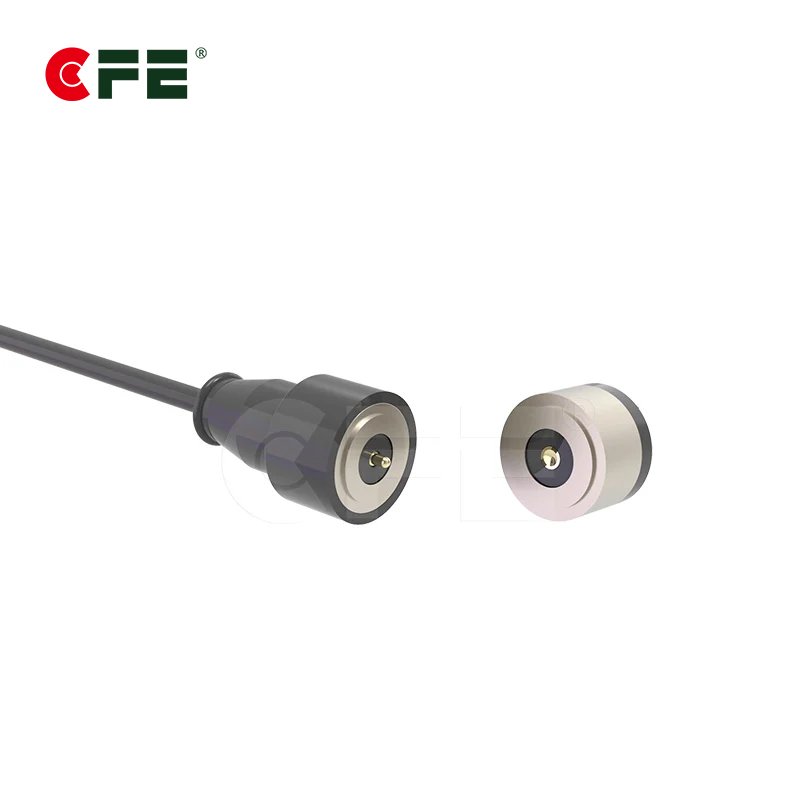
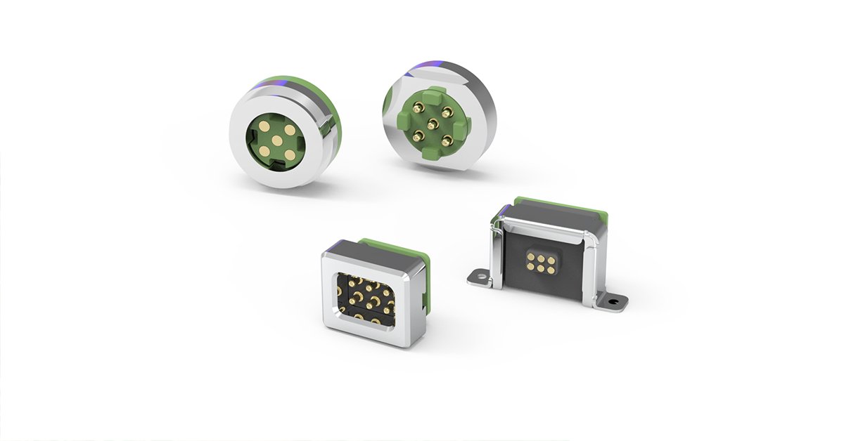
Magnetic connector retention force is the amount of force it takes to pull a mated magnetic connector apart. It sounds like a single number on a datasheet. In practice it is a balance: the magnet pulls the halves together, while pogo pin springs and seals push them apart. Get that balance wrong and you either ship a product that drops its charge connection when someone bumps the desk, or one that nobody can unplug with one hand.
If you buy connectors for a living, this guide will help you ask better questions before you request samples. It also pairs with our overview of waterproof pogo pin and magnetic connectors for 5A–30A designs, where current rating and sealing come into the picture.

What Retention Force Really Means
Retention force is the pull required to separate two mated connector halves, measured along a defined direction and at a defined condition. Every part of that sentence matters. “Defined direction” because the same connector can survive a hard straight pull and still pop off from a sideways tug. “Defined condition” because temperature, wear, and contamination all change the result.
Here is the first thing many buyers miss: the figure a magnet supplier quotes is usually the magnet’s own pull against a flat steel plate, in ideal contact. That is not your connector’s retention force. Once you add an air gap, a plastic housing wall, a waterproof gasket, and spring-loaded pins pushing back, the usable number is lower, sometimes a lot lower.
So when you write a specification, ask for the assembled connector’s retention force, not the magnet’s rating. That single change in wording avoids most of the disappointment we see between prototype and production.
Pull, Shear, and Peel: Three Ways a Connector Lets Go
A magnetic connector is rarely loaded in a perfectly straight line. Think of a charging cable on a rugged handheld. It gets tugged, dragged across a table, and stepped on. Each of those loads acts differently on the joint.
- Axial pull: the force acts straight along the mating axis. This is what most datasheets report.
- Shear (lateral) load: the force slides one half sideways across the other. Magnets resist sliding mainly through friction and any mechanical alignment features, so shear holding is often much weaker than axial pull unless the housing locks the halves laterally.
- Peel or tilt: one edge lifts first, and the joint opens like a hinge. Because magnetic attraction falls off quickly with distance, once one edge opens, the rest tends to follow.
Peel is the failure that surprises people. A connector can have a respectable axial rating and still disconnect easily when the cable pulls at an angle. If your product’s cable exits sideways, test for it specifically.
Practical tip: ask the supplier which direction the quoted number represents, and request values for at least axial and angled pull. If you are designing the housing yourself, a small guide lip or pocket that locks out sideways movement does more for real-world holding than a bigger magnet.

The Magnet Side: Grade, Size, Gap, and Backing Steel
Four variables control how hard the magnets pull.
Magnet size and grade. A larger magnet, or a higher-grade material, pulls harder. Most compact connectors use neodymium magnets because of their strength for the size. The trade-off is temperature: neodymium loses strength as it heats, and each grade has its own maximum working temperature. A connector sitting next to a hot battery or in a sun-baked vehicle needs a grade chosen for that environment.
Air gap. This is the big one. Magnetic pull drops steeply as the distance between the magnet and its mate increases. Every fraction of a millimeter of housing wall, gasket, or coating between the magnet and the mating surface costs you force. When a design review says “we just need a slightly thicker front wall for strength,” the retention force is quietly taking a hit.
Backing steel. A steel plate or cup behind a magnet concentrates the field toward the mating face. That is why many connectors seat the magnet in a steel pocket. It increases pull on the working side and reduces the field leaking out the back.
Pole arrangement. Magnets in the pair are normally arranged so opposite poles face each other. Alternating polarity layouts also act as a built-in polarity key, so the connector only mates one way. That matters for power connectors where reversed polarity would be a problem.
One more consequence to plan for: stronger magnets mean stronger stray fields. If your device carries a compass, hall sensor, or other magnetically sensitive part, read our guide to magnet stray fields and protecting sensors before you choose the magnet size.
The Pogo Pin Side: Springs Push Back
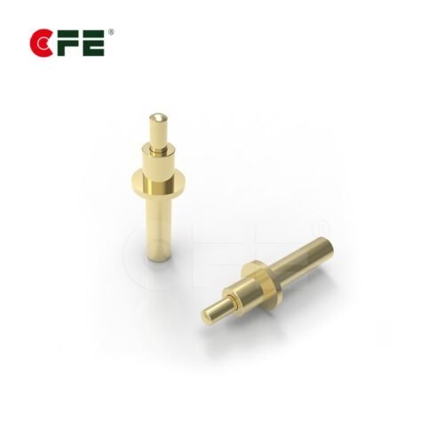
Here is where a pogo pin magnetic connector differs from a plain magnetic catch. Each pogo pin contains a spring that presses the plunger against its mating pad. That spring force is what keeps electrical contact stable, but it also tries to push the two halves apart.
Net retention force is roughly the magnet attraction minus the combined spring force of all pins, minus any seal compression force. Add more pins and the spring load grows. A four-pin connector and a twelve-pin connector can use identical magnets and behave very differently.
Contact quality works against you from the other side. Lower spring force means lower contact pressure, and lower contact pressure can mean higher or less stable contact resistance, especially under vibration or if the pad surface is slightly dirty. So you cannot simply pick the softest spring to boost retention. The goal is the lowest spring force that still keeps contact resistance stable for your current level.
That is also why high-current designs need extra care. If you are weighing how pin count, pin rating, and current interact, our 5A–30A high current pogo pin range shows how pin ratings scale, and the choice of brass, beryllium copper or phosphor bronze affects spring behavior too.

Waterproof Seals Take a Share of the Force
If your product has an ingress protection target, the connector face probably includes a gasket or O-ring. A good seal needs compression to work, and compression means the seal is also pushing the halves apart. The magnet has to overcome that as well.
There is a design tension here. Too little compression and the seal may leak. Too much and your magnets are fighting the gasket all day, which raises the force needed to hold the connector together and can make mating feel mushy. Seal hardness, groove geometry, and the compression ratio all feed into the final retention figure. The plastic around it matters as well, which we cover in pogo pin housing materials: LCP vs. high-temp PA.
Buyers sometimes ask for “IP67” or “IP68” as if it were a connector property. It is a rating applied to a tested assembly under defined conditions. The IEC explanation of IP ratings is a useful reference when you write that requirement into your specification. For connectors, confirm whether the rating applies when mated, unmated, or both, because those are different tests with different risks.
If water exposure is part of your use case, we cover the full picture, from current rating to sealing, on our waterproof pogo pin and magnetic connector page.
A Simple Retention Budget (Illustrative Example)
Let’s walk through the logic with made-up numbers. These are for illustration only and are not CFE product specifications.
| Item | Effect on retention | Example value |
|---|---|---|
| Magnet pull at working gap | Adds holding force | +10 N |
| Pogo pin springs (all pins combined) | Pushes halves apart | −3 N |
| Gasket compression | Pushes halves apart | −2 N |
| Net axial retention | What the user feels | about 5 N |

Notice what happened. A 10 N magnet delivered about half that in practice. Now imagine a design change that adds two more pins and a thicker front wall. The spring load rises, the gap grows, and the net figure could fall well below what your drop and tug tests require.
The takeaway: build the budget early, with real component data, and update it whenever the pin count, housing thickness, or seal changes. Then validate with physical samples, because tolerances stack in ways spreadsheets miss.
Temperature, Vibration, and Wear Over Time
A connector that passes on the bench on day one is not yet a connector that works in the field. Three factors erode retention over a product’s life.
- Temperature: heat reduces magnet strength, and the loss depends on the grade. Cold can stiffen seals and change how they compress. Specify both ends of the operating range, and ask the supplier at which temperature the retention figure was measured.
- Vibration and shock: in vehicles, drones, and industrial equipment, the connector sees repeated micro-movement. Retention must hold the halves firmly enough that the pins do not chatter against the pads, which can cause intermittent contact.
- Contamination and wear: dust, lint, or metallic debris collected on the mating face can raise the gap, and ferrous particles can even be attracted to the magnet. Plating wear on pads and pins changes contact behavior after many cycles. Our notes on pogo pin gold plating thickness explain how plating relates to cycle life.
If your product is expected to survive thousands of mating cycles, ask for cycle test data on both retention and contact resistance, not just one of them.
Choosing a Target Retention Range by Application
There is no universal “right” retention force. The goal is to be strong enough to stay connected under realistic disturbance and gentle enough that a user, or a safety requirement, can break the connection easily. The table below describes the thinking, not specific numbers.
| Application | Design priority | Typical concern |
|---|---|---|
| Wearables and small handhelds | Easy one-hand release | Accidental disconnect during movement |
| Charging docks and cradles | Self-alignment, stable contact | Cable drag pulling device off the dock |
| Vehicles, drones, and robots | Hold under vibration | Intermittent contact and shock |
| Outdoor or wet equipment | Sealed, repeatable mating | Seal compression and contamination |
A useful rule: decide whether you want the connector to act as a breakaway (it should release before the cable or device is damaged) or as a secure hold (it should stay put under load). Many products need a bit of both, and the housing design can tune the balance. A breakaway design protects the device from a yanked cable, which is a common cause of field returns for portable electronics.

How to Specify and Test Retention Force
A vague requirement such as “strong magnetic hold” invites a vague answer. Write the requirement so a supplier and your own lab measure the same thing.
- State the pull direction (axial, angled, lateral) and the angle if relevant.
- State the test speed and fixture, because pulling faster or slower can change the reading.
- State the temperature and condition (new, after cycle test, wet, dusty).
- Define pass criteria as a range with a minimum and a maximum, not just a minimum.
- Ask for contact resistance measured while the connector is under a defined load, so you see retention and electrical stability together.
For testing, a force gauge on a motorized or manual stand works well, provided the fixture holds the connector squarely. A crooked fixture adds peel loading and gives you a lower, noisier number. Measure several samples, not one, and record the spread. A supplier that can share the test method and a few measured values is easier to design with than one that shares only a single headline figure.
Common Mistakes Buyers and Designers Make
- Trusting the bare magnet rating. The assembled connector delivers less, as the budget above shows.
- Changing the housing late. A thicker wall or added coating raises the air gap. Recheck retention after every mechanical revision.
- Ignoring the cable. Cable stiffness, weight, and exit angle load the joint in ways a straight-pull test never sees. Wire gauge changes stiffness too, see AWG vs. mm² cable for 5A–30A magnetic connectors.
- Forgetting the maximum. Too much retention can be a safety or usability problem. Set an upper limit too.
- Skipping environmental checks. Hot, cold, wet, and dusty conditions each shift the result.
Questions to Ask Before You Request Samples
A short, specific message gets better answers. When you contact a connector supplier, include your operating current, voltage, pin count, ingress protection target, temperature range, cable exit direction, and the pull scenario you worry about most. Then ask for measured retention in that scenario, the magnet grade and its temperature limit, and the pin spring force. If you would like to talk through a design, you can start from the CFE website or go straight to the waterproof 5A–30A connector range and send your requirements.
Conclusion
Retention force is not a property you read off a magnet datasheet. It is the result of a system: magnet strength at the real working gap, minus the push-back of pogo pin springs and seals, tested in the direction and conditions your users will actually create. Build a simple budget early, test pull, shear, and peel on assembled samples, and write a specification with both a minimum and a maximum. Do that, and the connector will feel right in the hand and stay connected when it should.
Frequently Asked Questions
What is a good retention force for a magnetic pogo pin connector?
It depends on the product. A wearable needs a light hold that releases easily, while a vibrating vehicle mount needs a firmer one. Start from the worst realistic disturbance, such as a cable tug, and set a minimum above it. Then set a maximum so users can still disconnect comfortably.
Does adding more pogo pins reduce retention force?
Generally, yes. Each spring-loaded pin pushes the halves apart, so more pins raise the opposing force and lower the net retention for the same magnets. You can compensate with stronger magnets or lower-force springs, but check contact resistance when you reduce spring force.
Why is the retention force lower than the magnet’s rated pull?
Magnet ratings are usually measured against a steel plate in direct contact. In a real connector there is a housing wall, possibly a gasket, and an air gap, and magnetic pull falls off quickly with distance. Springs and seals also push back, so the net figure is lower.
Do magnetic connectors weaken over time?
Permanent magnets keep most of their strength under normal conditions, but heat can reduce it, and retention can change if the seal wears or debris builds up on the mating face. Ask for cycle and temperature test data if your product has a long service life.
How should I test retention force?
Use a force gauge with a fixture that holds the connector squarely, pull at a defined speed and direction, and test several samples at your operating temperatures. Include an angled pull to capture peel behavior, and record contact resistance under load.