
The world of wireless power and compact docking solutions is moving fast. As devices demand higher power and more reliable data transfer through smaller interfaces, traditional contact technologies are being pushed to their limits. CFE-CONN’s 5A–30A high-current pogo pins answer that call: they’re compact, spring-loaded contacts engineered to carry significant current while maintaining low resistance, durability, and reliable mechanical engagement. In short, they’re quietly changing how engineers design wireless charging systems, rugged connectors, and modular device interfaces.
What makes a pogo pin “high-current”?
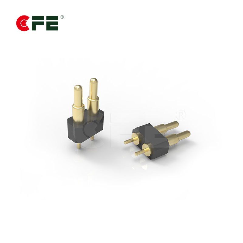
Pogo pins are spring-loaded contacts that complete electrical connections when two mating surfaces press together. Most pogo pins are designed for signal-level currents (mA to low A).
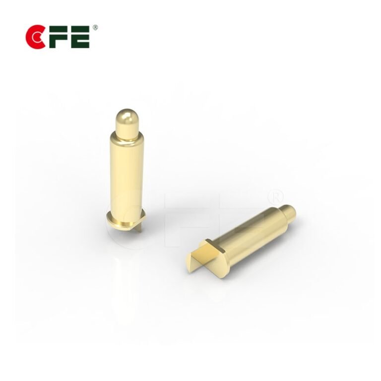
CFE-CONN’s 5A–30A pogo pins differ in these ways:
-
Contact geometry and plating are optimized to reduce contact resistance at higher currents.
-
Robust internal springs that maintain consistent contact force under repeated cycles and vibration.
-
Heat-tolerant materials and structures that minimize thermal rise under sustained loads.
-
Larger contact area or specialized tip designs to spread current and lower localized heating.
These design choices let an otherwise small, spring-operated connector handle currents previously reserved for much bulkier connector families.
Why that matters for wireless charging and docking
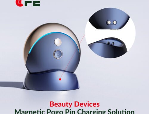
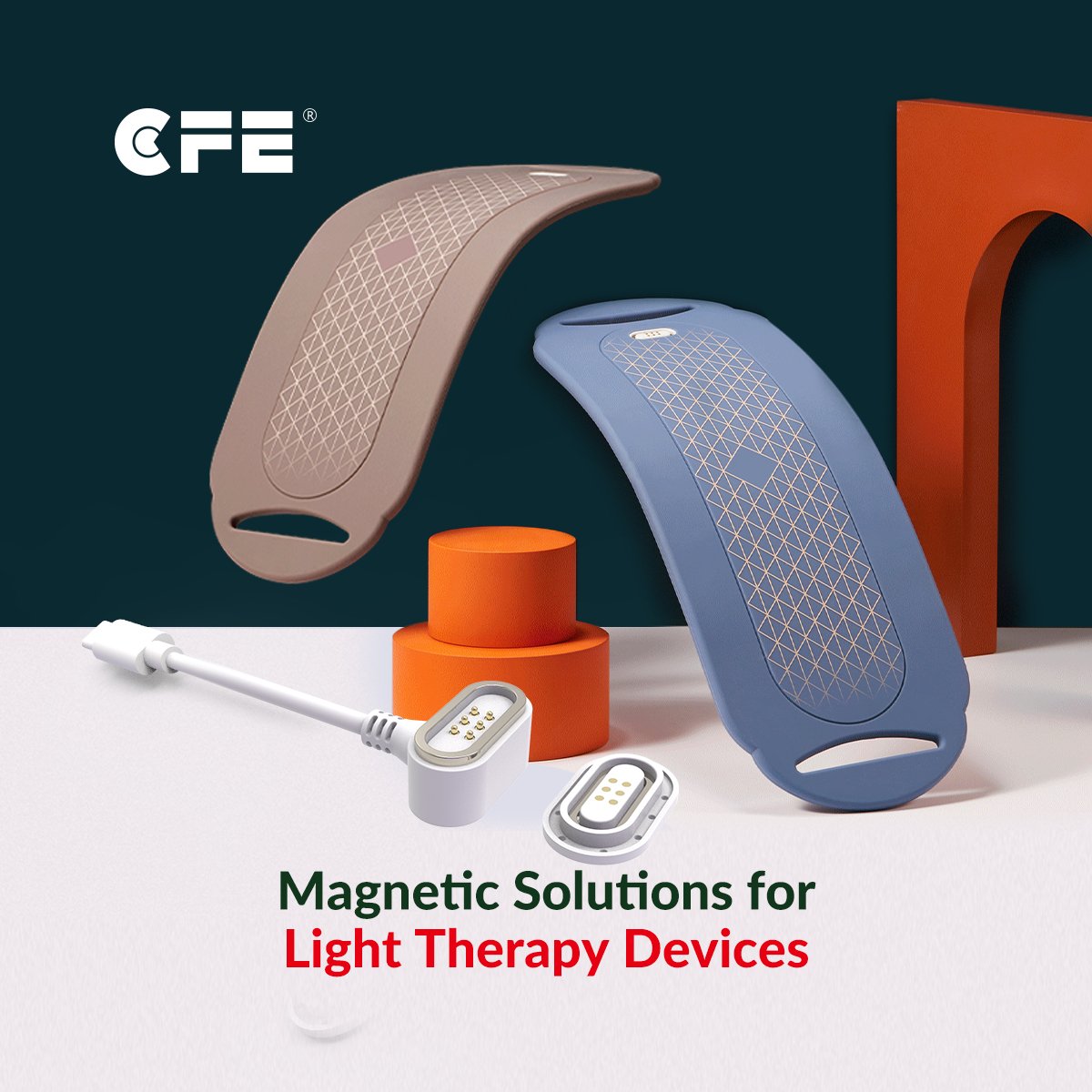
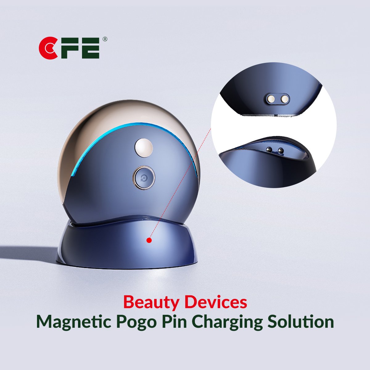
Wireless charging — whether inductive pads, magnetic mounts, or hybrid systems — increasingly relies on magnetic alignment plus metal contacts for higher-power “fast charge” operation, accessory power, or data handshakes. High-current pogo pins let designers:
-
Offload high-power paths safely and compactly.
-
Provide a redundant, low-impedance path during peak load (e.g., rapid charging bursts).
-
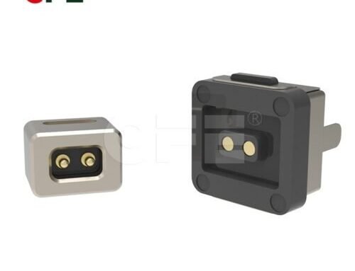
Enable modular accessories (docks, battery packs, or external sensors) that connect without bulky plugs.
-
Maintain reliable connections through wear, shock, and repeated mating cycles.
In consumer electronics, robotics, automotive accessory ports, and industrial IoT, that combination of power density and reliability is a differentiator.
Engineering benefits and real-world tradeoffs
Benefits
-
Space efficiency: Compared with screw terminals or heavy blade contacts, a set of pogo pins occupies less board space and has easier mechanical integration.
-
Serviceability: Spring-loaded pins allow quick connect/disconnect without tools, ideal for field-replaceable modules or hot-swap accessories.
-
Consistency: Good pogo pins maintain low and repeatable contact resistance over thousands of cycles, which is essential for predictable thermal and electrical behavior.
-
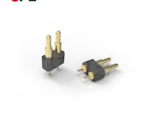
Integration flexibility: Pogo pins can be arranged in arrays to carry multiple power rails, ground, and data lines in a single compact zone.
Tradeoffs
-
Thermal management: At 30A, even low resistance creates heat. Designers must pair pogo pins with thermal paths and correct PCB/thru-hole reinforcements.
-
Mechanical alignment: High-current pogo pins often work best with precise mechanical guides or magnetic alignment to avoid side-loading and tip wear.
-
Cost: High-current pogo pins use better materials and springs; they cost more than general-purpose signal pogo pins.
Smart design accounts for these tradeoffs — placing pins on reinforced pads, using heat-spreader planes, and designing mating hardware that shares load across multiple pins.
Typical applications transforming industries
-
High-power wireless chargers for handhelds and tablets where pogo pins provide a backup or supplemental high-current path during fast-charging cycles.
-
Modular battery packs for drones and handheld tools where quick connection and disconnection, plus high current, are required.
-
Automotive accessory docks where vibration resistance and high current are mandatory.
-
Medical devices require reliable power contacts for charging and data transfer with frequent connect/disconnect cycles.
-
Industrial robots and AGVs that need rugged, repeatable high-current connections for charging or tool exchange.
Design tips for integrating 5A–30A pogo pins
-
Use multiple pins for high currents: Instead of routing 30A through a single pin, distribute the current across several contact pins to reduce the heat per pin.
-
Plan thermal dissipation: Connect pins to copper pours, thermal vias, or a heatsink to spread heat away from the contact region.
-
Reinforce the PCB landing by using through-hole anchors, thicker copper, or metal plates to prevent pad delamination under repeated cycles.
-
Include alignment features: MX magnets, locating pegs, or guide slots help keep mating faces perfectly aligned, reducing wear and ensuring contact integrity.
-
Test at operational temperatures: Validate contact resistance and mechanical life across the worst-case temperature range your product will see.
Why CFE-CONN stands out
CFE-CONN’s pogo pins target the intersection of mechanical reliability and electrical performance. Their 5A–30A range indicates a focus on high-throughput applications. Key differentiators include:
-
Tip and plating options tuned for low resistance and corrosion resistance.
-
Spring designs that resist relaxation and maintain contact force over many cycles.
-
Manufacturing tolerances that support consistent performance in arrays — important when several pins share current.
For product teams, that means fewer surprises in prototyping and a smoother path to production.
FAQs
Q1: Do high-current pogo pins need special plating?
A: Yes. Platings like gold over nickel or specific silver alloys can lower contact resistance and protect against fretting corrosion. The optimal plating balances conductivity, wear resistance, and cost.
Q2: How many mating cycles can I expect?
A: High-quality pogo pins typically guarantee thousands to tens of thousands of cycles. The exact lifecycle depends on environmental conditions, force, and alignment quality.
Q3: Are these pins suitable for automotive use?
A: Many high-current pogo pin designs meet or can be designed to meet automotive standards for vibration, temperature, and corrosion. Always check supplier specs and certifications.
Q4: Will a pogo pin array interfere with wireless coil performance?
A: Not inherently. Proper mechanical layout and EMI shielding can prevent the pins from introducing loss into the coil. In some hybrid designs, the pogo pins are offset or shielded to minimize interaction.
Conclusion
CFE-CONN’s 5A–30A high-current pogo pins give engineers a practical way to combine compact form factors with substantial power capability. For wireless charging, modular docking, and rugged accessory interfaces, these pogo pins let designers achieve space and mechanical simplicity without sacrificing electrical performance. The trick is to design around thermal and mechanical realities — distribute current, reinforce landings, and provide alignment — and the result is a lightweight, reliable connection strategy that truly does help shape the wireless future.
