
As electronic devices continue to evolve toward miniaturization, modular design, and high reliability, stable interconnect solutions have become a critical requirement in modern hardware engineering.
Pogo Pins (also known as spring-loaded pins, spring contacts, or spring-loaded electrical connectors) are widely used in precision electronic systems where repeated mating cycles, compact layout, and stable conductivity are required.
1. What Is a Pogo Pin?
A Pogo Pin is a spring-loaded electrical contact component designed to establish reliable electrical conduction between two mating surfaces through controlled mechanical compression.
It enables temporary yet highly stable electrical connections without requiring soldered or permanent joints.
1.1 Core Structure of a Pogo Pin
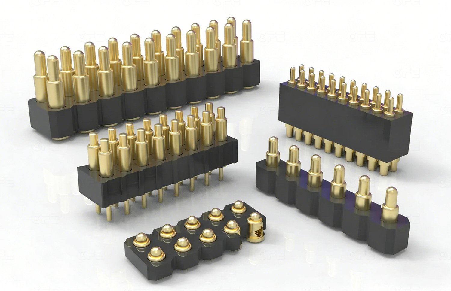
A standard Pogo Pin consists of three precision-engineered components:
• Barrel (Housing)
The outer metal tube that supports the internal mechanism and provides structural integrity for PCB mounting or solder integration.
• Plunger (Contact Tip)
The movable conductive tip that directly interfaces with the mating surface to transmit electrical signals or power.
• Compression Spring
A precision spring that provides constant force, ensuring stable contact pressure and low-resistance conductivity during operation.

1.2 Working Principle
When external pressure is applied:
- The plunger retracts into the barrel
- The spring compresses and stores mechanical energy
- Stable contact force is maintained between mating surfaces
- Low-resistance electrical conduction is ensured even under movement or vibration
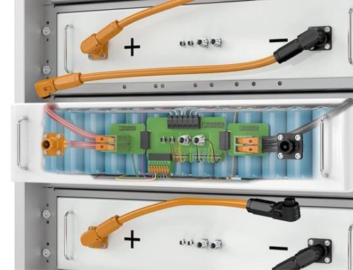
2. Common Pogo Pin Structures and Types
Different engineering applications require different mechanical configurations of Pogo Pins. The following table summarizes the most commonly used industrial designs:
| Pogo Pin Type | Technical Description | Engineering Advantages |
|---|---|---|
| Through-Hole | Includes positioning pin for alignment control | High assembly accuracy, prevents PCB misalignment |
| Right Angle/Bend | Bent terminal for space-constrained routing | Enables compact PCB layout design |
| SMT | SMT-compatible design with flat mounting base | High stability, optimized for PCB assembly automation |
| Double Head | Conductive ends on both sides | Supports board-to-board and modular connections |
| Solder Cup | Wire connection interface via solder cup | Strong mechanical and electrical wire bonding |
3. Key Advantages of Pogo Pins
3.1 High Reliability Electrical Contact
Pogo Pins maintain consistent contact force through spring tension, ensuring stable performance in environments with:
- Vibration
- Mechanical shock
- Frequent mating cycles
3.2 Extended Mechanical Lifespan
High-quality Pogo Pins are engineered for long operational durability:
- 100,000+ cycles (standard grade)
- 500,000+ cycles (industrial grade)
- 1,000,000+ cycles (high-end precision grade)
3.3 Compact and Miniaturization-Friendly Design
Their small footprint makes them ideal for next-generation compact electronics such as:
- Wearable devices
- IoT sensors
- Smart medical instruments
- AR/VR hardware
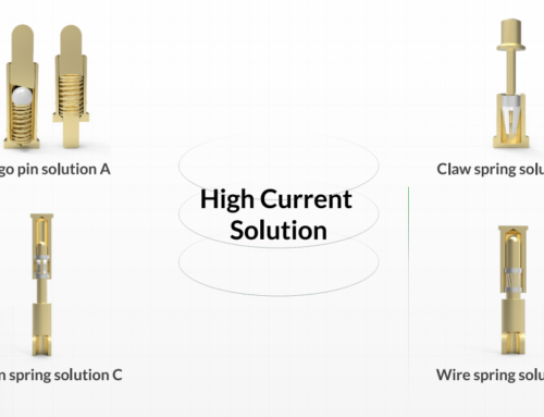
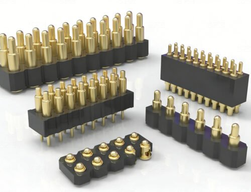
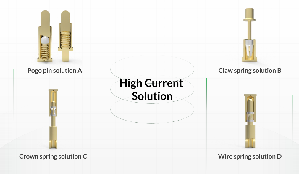
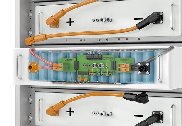
3.4 High Current Transmission Capability
Depending on design optimization, Pogo Pins can support:
- 5A standard current
- 10A–20A medium-high current
- Up to 60A in specialized configurations
3.5 Ideal for Magnetic Connector Systems
Pogo Pins are widely integrated into magnetic interconnect systems, enabling:
- Automatic alignment (self-guiding connection)
- Blind mating capability
- Enhanced user experience in charging docks and accessories

4. Pogo Pin Selection Guide
Selecting the correct Pogo Pin requires evaluating multiple electrical and mechanical parameters:
4.1 Electrical Requirements
- Rated current capacity
- Operating voltage
- Signal integrity requirements
- High-speed data transmission needs
4.2 Mechanical Design Constraints
- Available vertical height
- Pin pitch (spacing density)
- PCB layout restrictions
- Mounting method (SMT / THT / press-fit)
4.3 Environmental Reliability
- Corrosion resistance (plating material selection)
- Waterproof or sealed design requirements
- Shock and vibration tolerance
- Temperature range stability
4.4 Lifecycle Requirements
- Required mating cycles
- Contact resistance stability over time
- Spring fatigue resistance
4.5 Custom Engineering Requirements
Custom pogo pin solutions are commonly required for:
- Magnetic charging interfaces
- Waterproof electronic connectors
- High-current power modules
- Ultra-compact wearable devices

5. FAQ
Q1: What is a Pogo Pin used for?
A Pogo Pin is used to create a reliable temporary electrical connection between two electronic components, enabling power or signal transmission without permanent soldering.
Q2: Why are Pogo Pins used in magnetic connectors?
Because their spring-loaded structure allows automatic alignment and consistent contact pressure, making them ideal for magnetic charging and docking systems.
Q3: What factors affect Pogo Pin durability?
Durability depends on contact material, spring quality, plating thickness (such as gold plating), operating environment, and total mating cycle count.
Conclusion
Pogo Pins are a critical interconnection technology in modern electronics, enabling compact, durable, and high-reliability electrical connections across a wide range of applications.
With continuous trends toward device miniaturization, modular architecture, and magnetic interfaces, Pogo Pin technology will remain an essential component in future electronic design and industrial connectivity systems.
