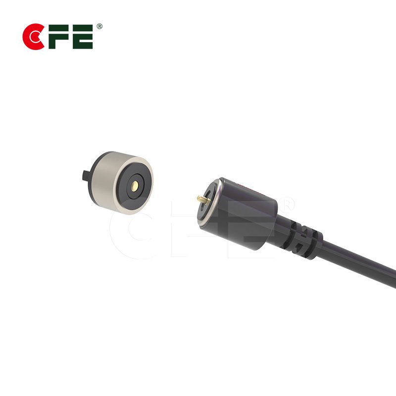
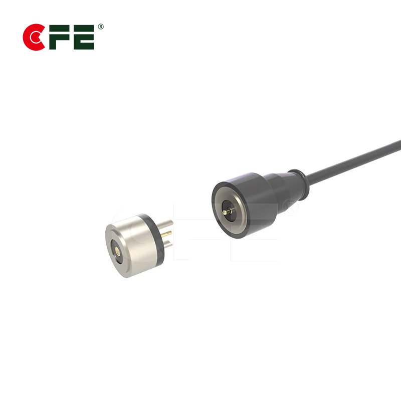
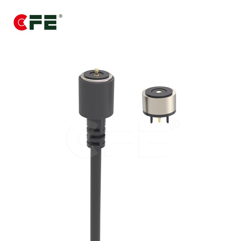
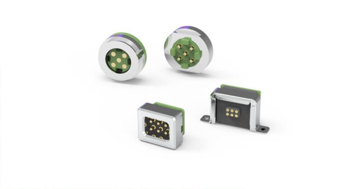
OEM connector tooling is the set of molds, stamping dies, plating fixtures, test jigs and inspection gauges that turn an approved connector design into a repeatable production part. Once that hardware is cut and qualified, every change costs time, money and often a launch window.
This guide is written for B2B buyers and engineering teams. It covers what to lock down first, which tests to run, and how to avoid the late surprises that delay product launches. It also supports our range of waterproof pogo pin and magnetic connectors for 5A to 30A designs.
In this guide
- What OEM Connector Tooling Actually Covers
- Why Late Changes Cost So Much More Than Early Ones
- Run a Design-for-Manufacturing Review Before Tooling Release
- Housing Materials and Seal Design: Where Waterproofing Is Won or Lost
- Contact Plating and Pad Finish Decisions
- Current Rating, Cable Choice and Thermal Margin
- Prototype Validation: Tests to Run Before You Release Tooling
- First Article, Pilot Run and Production Controls
- A Practical Tooling Readiness Checklist
- Working With CFE on OEM Connector Programs
- Conclusion
- Frequently Asked Questions
What OEM Connector Tooling Actually Covers
Buyers often hear “tooling” and think only of the plastic mold. In practice, a pogo pin or magnetic connector program involves several separate tool families, and each one has its own cost, lead time and owner.
- Injection molds for housings, carriers and insulators.
- Stamping dies for contact springs, shells and terminals.
- Turning and plating setups for barrels and plungers, including racks and process recipes.
- Assembly fixtures that position springs, pins and magnets consistently.
- Test fixtures and gauges for contact resistance, force, height and leak checks.
Knowing the full list matters because a quote that covers only the mold hides real costs. Ask your supplier to itemize every tool family, state who owns it, and say where it will be stored. For standard pitches and custom layouts, our custom pogo pin connector page shows the kind of variations that can be built around a common platform.

Why Late Changes Cost So Much More Than Early Ones
Think of tooling like pouring concrete. You can move a drawing line for free, but you cannot move a wall after the slab has set. A mold that has already been cut can usually have material removed. Adding material is far harder, often requiring inserts, welding or a new cavity.
That asymmetry is why the best OEM programs front-load decisions. A change at the drawing stage costs an engineer’s afternoon. The same change after tooling release can mean a mold modification, a new sample round, retesting and a slipped schedule. Re-qualification is the part teams underestimate, because every changed dimension can invalidate earlier test data.
Here is the practical rule we share with buyers: freeze the interfaces first and the details later. Interfaces are anything that touches another part of your product, such as the PCB footprint, the enclosure opening, the mating cable and the charging dock. Internal details like fillet radii can move more freely, but interface changes ripple through your whole assembly.
Run a Design-for-Manufacturing Review Before Tooling Release
A design-for-manufacturing (DFM) review is a structured conversation between your engineers and the supplier’s tooling team. Its job is to find problems while they are still cheap. Bring a complete package, not a rough sketch.
- Drawings with tolerances on every functional dimension, marked as critical or reference.
- Operating environment, including temperature range, moisture exposure, vibration and expected mating cycles.
- Electrical targets: working current, voltage, allowable contact resistance and temperature rise.
- Assembly method: SMT reflow, through-hole, solder cup or cable termination.
- Compliance needs, such as materials restrictions or customer-specific test standards.
Be specific about volume, too. A program planning a few thousand units a year may justify a single-cavity mold, while one planning hundreds of thousands usually needs multiple cavities and automated assembly. Share your forecast, including a realistic ramp, so the supplier can size the tooling to match instead of guessing.
A good supplier will push back. Expect questions about wall thickness, draft angles, gate locations and whether a tolerance is realistic for the chosen material. If a supplier approves every drawing without comment, treat that as a warning sign rather than good news. You can see how we structure this early engineering work on our services page.
Housing Materials and Seal Design: Where Waterproofing Is Won or Lost
For waterproof connectors, the housing and seal design decide most of the outcome. A pogo pin can have excellent contact performance and still fail a leak test because of a thin wall, a poorly placed gate or a seal groove that does not compress evenly.
Material choice sets the baseline. Heat-resistant housings behave differently in reflow, humidity and long-term creep, which is why we wrote a full comparison of LCP versus high-temperature PA for pogo pin housings. Seal design then adds its own questions: compression range, groove geometry, and what happens when the product is mated at an angle.
When you specify “waterproof”, be exact. State the required ingress rating, the test method and the duration. The IP code system is a common reference, but remember that an IP rating applies to a tested assembly in a stated condition, not to a part on its own. Our waterproof pogo pin page notes that the inner structure can be adapted to a customer’s sealing needs.

Contact Plating and Pad Finish Decisions
Plating is easy to treat as a cosmetic line item, yet it controls contact resistance, wear life and corrosion resistance. Because plating thickness is set in the process recipe rather than the mold, it can look flexible. It is not. Changing it later affects cost, test results and sometimes mating behavior.
Decide three things early: the base metal, the underplate and the gold thickness. Our guide to pogo pin gold plating in microinches versus microns clears up a unit confusion that causes real quoting errors between teams.
The mating surface matters just as much. If your PCB pads use a thin finish, even a perfect pogo pin will wear through them quickly. Compare options in our article on ENIG versus hard gold contact pad finishes, and agree on the finish before you finalize the board layout.
Current Rating, Cable Choice and Thermal Margin
High-current designs need more than a bigger pin. A connector rated for a given current in a datasheet may run hotter in your enclosure, where airflow is limited and neighboring components add heat. Always ask for temperature-rise data under conditions that resemble your product.
Cable selection is part of the same decision. A mismatch between the cable gauge and the contact rating moves the hot spot from the connector to the wire. Our explainer on AWG versus mm² for 5A to 30A magnetic connectors helps teams choose the right conductor size without unit mix-ups.
For multi-pin designs, spacing and insulation also matter. Review our notes on preventing short circuits in multi-pin connectors and magnetic connector polarity before locking the layout. If you are working in this range, browse our 5A-30A high current pogo pins and 5-30A magnetic connectors.

Prototype Validation: Tests to Run Before You Release Tooling
Prototype samples are cheap compared with production tooling, so use them hard. Build a validation plan that mirrors real use, and write the pass criteria down before testing starts. That way, results cannot be reinterpreted after the fact.
| Test | What it proves | Related reading |
|---|---|---|
| Contact resistance | Electrical quality across mating cycles | Pad finishes |
| Temperature rise at rated current | Thermal margin inside your enclosure | Cable sizing |
| Salt spray or humidity exposure | Corrosion resistance of plating | ASTM B117 vs. ISO 9227 |
| Water or dust ingress | Seal performance as assembled | Waterproof range |
| Retention and pull force | Magnetic hold and accidental disconnect risk | Retention force guide |
| Durability cycling | Spring and plating wear over life | Gold plating |
Salt spray deserves a special note. Two standards are widely quoted, and they are not interchangeable, so confirm which one your customer expects. Our comparison of salt spray testing for pogo pins explains the differences in plain terms.
First Article, Pilot Run and Production Controls
After tooling is released, the first parts off the tool are not the finish line. They are evidence. A first article inspection compares measured parts with the drawing, and a pilot run shows whether the process stays stable across many pieces and several shifts.
Ask for a clear approval gate between each stage. A short list works well:
- First article report covering all critical dimensions.
- Pilot lot large enough to reveal process drift, not just a handful of parts.
- Agreed inspection plan with sampling levels and reaction rules.
- Change control, so no material, plating or process change happens without written notice.
Keep the first article report and pilot data on file. When a field issue appears months later, that record lets both teams trace the cause quickly instead of arguing over what changed.
If your connectors are soldered to a board, inspection after assembly also matters. See our guide to pogo pin solder joint inspection for OEM production, and learn more about our approach on the quality page.
A Practical Tooling Readiness Checklist
Use this table as a final gate before you sign off the tooling release. If any row is unclear, pause and resolve it first.
| Area | Confirm before release | Why it matters |
|---|---|---|
| Drawings | Critical dimensions and tolerances marked, revision controlled | Keeps your team and the supplier building to the same version |
| Materials | Housing, contact and magnet materials agreed in writing | A later material change can invalidate earlier test results |
| Plating | Base metal, underplate and gold thickness specified | Sets contact resistance, wear life and corrosion performance |
| Sealing | Rating, test method and duration defined | A rating only holds for the tested assembly and conditions |
| Electrical | Current, resistance and temperature-rise targets set | Keeps the hot spot out of your enclosure and cable |
| Tool ownership | Owner, storage location and maintenance plan documented | Avoids disputes over access, repair and transfer of tools |
| Approval gates | First article, pilot run and change control agreed | Turns the first production parts into documented evidence |
Working With CFE on OEM Connector Programs
Founded in 2009, Dongguan CFE Electronic Co., Ltd. develops and manufactures pogo pin, magnetic connector, magnetic cable and precision stamping solutions, with a focus on demanding conditions such as high current, waterproof and dustproof, and long life. Our certifications and module solutions are listed on the site, and our automotive and medical application pages show how requirements differ by market.

Conclusion
Connector tooling rewards teams that decide early and test honestly. Define the full tool list, freeze interfaces first, review the design for manufacturing, and validate with real samples before steel is cut. Then use first article and pilot gates to prove the process, not just the part. Done well, this approach protects your schedule and your budget, and it gives your customers a connector that behaves the same on the ten-thousandth unit as on the first.
Frequently Asked Questions
What is OEM connector tooling?
It is the production hardware used to make a custom connector repeatably, including molds, stamping dies, plating setups, assembly fixtures and test gauges. The tooling is built from your approved design and drawings. Share your drawings through our contact page to discuss your program.
When should tooling be released for mass production?
Release it only after the design review is complete, interface dimensions are frozen, and prototype samples have passed your agreed validation tests. Releasing earlier saves a few weeks on paper but often costs far more in modifications. See how we handle early engineering on our services page.
Who owns the tooling in an OEM project?
Ownership is a commercial term, so settle it in writing before any payment. Also agree where the tools are stored, who maintains them, and how long the supplier keeps them after the last order. Ask us about tooling terms through our contact page.
Can tooling be changed after release?
Often yes, but not always. Removing material is usually simpler than adding it, and any change can require new samples and retesting. Interface changes are the most expensive, so lock those first. Review our quality approach or send us your change request.
How do I verify a connector is truly waterproof?
Specify the ingress rating, test method and duration up front, then test the connector as assembled in your product. A rating on a loose part does not guarantee the finished device will pass. Explore the waterproof 5A to 30A range for sealed designs.