A short circuit in a multi-pin connector rarely announces itself. It shows up as a charger that runs warm, a sensor reading that drifts after a humid week, or a returned unit with a browned corner on the housing. For a B2B buyer, the real cost is not the part. It is the field failure, the RMA queue and the conversation with your customer afterwards.
The good news is that shorts are predictable. Almost every one traces back to a handful of causes, and each cause has a design or sourcing answer. This guide walks through them in the order a buyer or design engineer would meet them.

How do you prevent short circuits in multi-pin connectors? Keep conductive paths apart and keep them dry. In practice that means five things:
- Specify pitch, creepage and clearance for your real voltage and environment.
- Seal or recess the contact area against moisture, dust and metal debris.
- Use keyed or magnetically polarized mating so pins cannot cross-connect.
- Choose housing materials and platings that resist tracking and corrosion.
- Add circuit-level protection and verify it with testing before release.
Where Short Circuits in Multi-Pin Connectors Actually Come From
Before you fix a problem, name it. When we review failed connectors with customers, the cause is almost never mysterious. It usually falls into one of the categories below, and the first step is working out which one applies to your product.
| Root cause | How the short forms | Typical fix |
|---|---|---|
| Moisture and contamination | A film of water, sweat or salt bridges neighboring pins; with DC bias, corrosion and metal migration can grow across the gap | Sealing, recessed contacts, corrosion-resistant plating |
| Conductive debris | Metal swarf, solder balls or foreign objects such as coins and keys touch exposed contacts | Recessed or shrouded contacts, clean assembly, dead-front power |
| Insufficient spacing | Pitch, creepage or clearance too small for the voltage and contamination level | Larger pitch, barriers, ribs between pins |
| Misalignment or wrong mating | Pins land on the wrong pads, or polarity is reversed | Keying, polarized magnets, guide features |
| Assembly defects | Solder bridges, stray cable strands, pinched insulation | Process control, inspection, strain relief |
| Overcurrent and heat | A hot contact softens or carbonizes the housing, creating a tracking path | Correct current rating, derating, thermally stable plastics |
Notice what is missing from the list: bad luck. Each row is a design decision someone made or skipped. That is encouraging, because it means you can review your own design against the table in an afternoon.
Design for Creepage and Clearance First
Clearance is the shortest distance through air between two conductive parts. Creepage is the shortest distance along an insulating surface between them. Clearance stops arcing through air; creepage stops current from crawling across a contaminated surface. Multi-pin connectors need both, and the creepage figure is the one teams most often shortchange.
The governing framework is IEC 60664-1, the basic safety standard for insulation coordination, which covers equipment up to 1,000 V AC or 1,500 V DC and defines how clearances, creepage distances and solid insulation are dimensioned (IEC publication overview). It links the distances you need to three inputs: working voltage, pollution degree, and the tracking resistance of the insulating material. Dirtier environments and higher voltages both demand more distance.
Two pins in an insulating housing. Clearance is the straight line through air between the pin tips; creepage is the longer path along the housing surface and around a rib.
Clearance (through air)
Creepage (along the surface, over the rib)
Pin A
Pin B
A rib between pins lengthens the creepage path without enlarging the connector.
Compact products rarely have room for more pitch, so use geometry instead. Molded ribs and barriers between pins lengthen the surface path. Recessing contacts below the housing face adds depth. Staggering high-voltage and signal pins separates the pairs most likely to cause trouble. For custom layouts, CFE’s custom pogo pin connector service lets you set pin positions and housing features around your actual voltage rather than a catalog default.
Seal Out Moisture, Dust and Debris
Water by itself is a poor conductor. The trouble starts when it carries salts, sweat or cleaning residue, and when DC voltage sits across the gap for weeks. That combination drives electrochemical corrosion and can slowly build conductive paths between pins that looked safely spaced on the drawing. This is why a connector that passes a clean-bench test can still fail in a humid warehouse or a wearable that sees daily perspiration.
There are three practical lines of defense. First, seal the interface: gaskets, over-molded bodies and sealed pin barrels keep liquid away from the contact area. If your device is exposed to splashes or washing, start from the waterproof pogo pin range instead of retrofitting a standard part. Second, drain and shed: contact faces that angle outward or sit proud of a recess let liquid run off instead of pooling between pins. Third, choose the right claim. IP ratings come from IEC 60529, which classifies the protection an enclosure gives against solid objects and water (IEC 60529 overview). Ask whether a rating applies to the mated connector, the unmated connector, or both, because unmated, energized contacts are where most field shorts begin.

Corrosion deserves its own line in your specification. Plating thickness and base metal decide how long contacts stay clean, and our guides on pogo pin gold plating and salt spray testing for pogo pins explain what to ask for and how to read a supplier’s test report.
Control Mating: Keying, Polarity and Power Sequencing
Many shorts are not caused by the environment at all. They happen at the moment of connection. A plug is inserted at an angle, rotated 180 degrees, or hot-plugged under load, and the wrong pins meet for a fraction of a second. In a product used by thousands of people, that moment will eventually happen.
Mechanical keying is the simplest answer: an asymmetric housing that only fits one way. Magnetic polarization goes a step further. In a magnetic connector the magnets pull the plug into alignment and can be arranged so that a reversed plug is repelled rather than seated. That is a large part of why magnetic connectors suit charging ports that users plug in blind, one-handed or in the dark.

Then add sequencing. Use longer ground pins so ground connects first and breaks last, and keep power off the contacts until a detect or handshake pin confirms a valid connection. This “dead-front” approach means exposed contacts are not live when a coin, key or metal swarf bridges them. It is one of the strongest protections for any open-contact charging design, and it costs a load switch and a few lines of firmware rather than a larger connector.
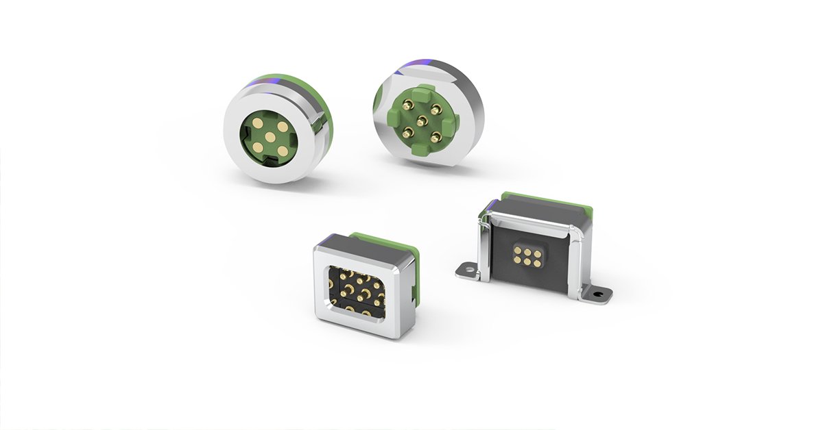
For multi-pin layouts, the 8-pin magnetic connector and multi-pin magnetic connector families are good starting points when you need power, ground and data in a single self-aligning interface.
Materials and Plating That Keep Insulation Intact
The housing is the insulation. If it deforms, cracks or carbonizes, your carefully calculated spacing no longer exists. Two properties matter most: dimensional stability at soldering and operating temperature, and resistance to surface tracking, the formation of conductive paths along a surface under electrical stress and contamination.
Engineering plastics such as LCP and high-temperature PA behave differently under reflow heat, moisture uptake and long-term stress, and the choice affects pin position accuracy as well as insulation. We compare them directly in Pogo Pin Housing Materials: LCP vs. High-Temp PA. A warped housing shifts pins toward each other, which is exactly what you cannot afford on a fine-pitch part.
On the metal side, base material and plating determine contact resistance and corrosion behavior. Spring strength also matters: a weak or fatigued spring leaves contacts bouncing, which causes arcing and heat. Our brass, beryllium copper and phosphor bronze comparison covers how each metal holds spring force over time.
Protect the Circuit and Prove the Design with Testing
Even a well-designed connector should assume that something, someday, will go wrong. Circuit-level protection turns a potential fire or dead board into a recoverable fault. Common measures include:
- Current limiting or short detection on every exposed power contact, with automatic shutoff.
- Resettable or one-time fuses sized to the cable and contact rating, not just the load.
- Soft-start or inrush control so hot-plugging does not stress the contacts.
- Conformal coating or potting on the PCB side to protect solder joints from moisture.
Do not forget the wire side. Undersized conductors overheat long before the connector does, so confirm cable sizing against current, as explained in AWG vs. mm²: Cable for 5A–30A Magnetic Connectors.
Then verify. A sensible short-circuit validation plan includes insulation resistance and dielectric withstanding checks between adjacent pins, humidity and temperature cycling, salt spray where corrosion is a risk, repeated mating cycles, and vibration. Run these on mated and unmated samples, because the two states fail in different ways. Ask your supplier for the actual reports, not a summary line on a datasheet.
A B2B Buyer’s Checklist for Short-Circuit Risk
If you source connectors rather than design them, the questions you ask in the RFQ do most of the prevention work. Here is a short list we suggest putting in front of any supplier, including us.
| Ask the supplier | Why it matters |
|---|---|
| What creepage and clearance does the part provide, and at what voltage? | Confirms spacing is rated for your working voltage, not just physically present |
| Is the IP rating for the mated state, unmated state, or both? | Unmated, energized contacts are the usual failure point |
| What housing material and plating are used? | Drives dimensional stability, tracking and corrosion resistance |
| How is reverse or misaligned mating prevented? | Keying and magnet polarity stop cross-connection |
| Which tests were run, and can I see the reports? | Evidence beats claims |
| What process controls cover the assembly line? | Prevents solder bridges and debris from shipping with the part |
CFE has manufactured pogo pin and magnetic connectors in Dongguan since 2009, with in-house R&D and quality control behind each program. You can review our quality system and certifications, and see how these principles apply in demanding fields such as medical and automotive connection solutions.
Designing for 5A to 30A in wet or dusty conditions? Our waterproof pogo pin and magnetic connectors (5A–30A) are built around sealing, spacing and polarized mating. Send us your voltage, current and environment, and our engineers will recommend a configuration. Request a quote and samples.
Conclusion
Preventing shorts in a multi-pin connector is not one clever trick. It is a stack of small decisions: enough creepage and clearance for the voltage, a sealed or recessed contact area, keyed or polarized mating, stable housing materials and durable plating, protective circuitry, and testing that reflects how the product is really used. Skip one layer and the others carry more load than they should.
If you are weighing options for a new program, start with the environment and the voltage, then work outward. And if you would rather start from a proven configuration, our team can help you match one to your application.
Frequently Asked Questions
What is the most common cause of short circuits in multi-pin connectors?
Contamination across closely spaced pins is the most common cause: moisture, salts, flux residue or metal debris bridging the gap. It often combines with insufficient creepage distance or corrosion that builds up over time under DC bias. Sealing, recessed contacts and adequate spacing address most of it.
What is the difference between creepage and clearance?
Clearance is the shortest distance through air between two conductors. Creepage is the shortest path along an insulating surface between them. Clearance prevents arcing through air; creepage prevents leakage and tracking across contaminated surfaces. Both must meet the requirements for your working voltage and environment.
Do magnetic connectors reduce the risk of short circuits?
They can. Magnets self-align the plug, and polarized magnet arrangements reject a reversed connection. Safety also depends on the rest of the design, so pair them with recessed contacts, power sequencing or a detect pin so exposed contacts are not live until a valid mate is confirmed.
Does an IP rating guarantee that a connector will not short?
No. An IP rating describes protection against solids and water under defined test conditions (IEC 60529). It does not cover every contaminant or every state of use. Check whether the rating applies to the mated or unmated connector, and still validate with your own humidity, corrosion and mating-cycle tests.
How can I add short-circuit protection to a charging connector?
Use a load switch or current-limit circuit that keeps contacts de-energized until a connection is detected, add a correctly sized fuse, and control inrush on hot-plug. Combine this with ground-first pin sequencing and conformal coating on the PCB side for a layered defense.