Here is something every connector engineer learns the hard way: the prototype is the cheapest place to be wrong. A drawing can look perfect on screen and still hide a footprint that is 0.1 mm off, a stroke that bottoms out too early, or a plating choice that wears through in a few months. Catch it at the sample stage and it costs you a week. Catch it after tooling and it costs you a quarter.
Custom connector prototyping is the process of turning a CAD design into physical sample connectors, testing them against your electrical, mechanical and environmental requirements, and approving a first article before tooling and mass production begin. This guide walks B2B buyers and design teams through each stage, from the first requirements brief to the signed-off sample, so you know what to prepare, what to ask for, and where projects usually stumble.

What Is Custom Connector Prototyping, and Why Does It Matter?
Think of prototyping as a conversation between your CAD model and reality. On screen, every dimension is exact. On the bench, springs have tolerances, plating has thickness ranges, and PCBs flex a little when someone presses a device into a dock. Prototyping is where those two worlds meet, and where you find out which assumptions survive.
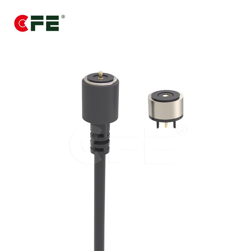
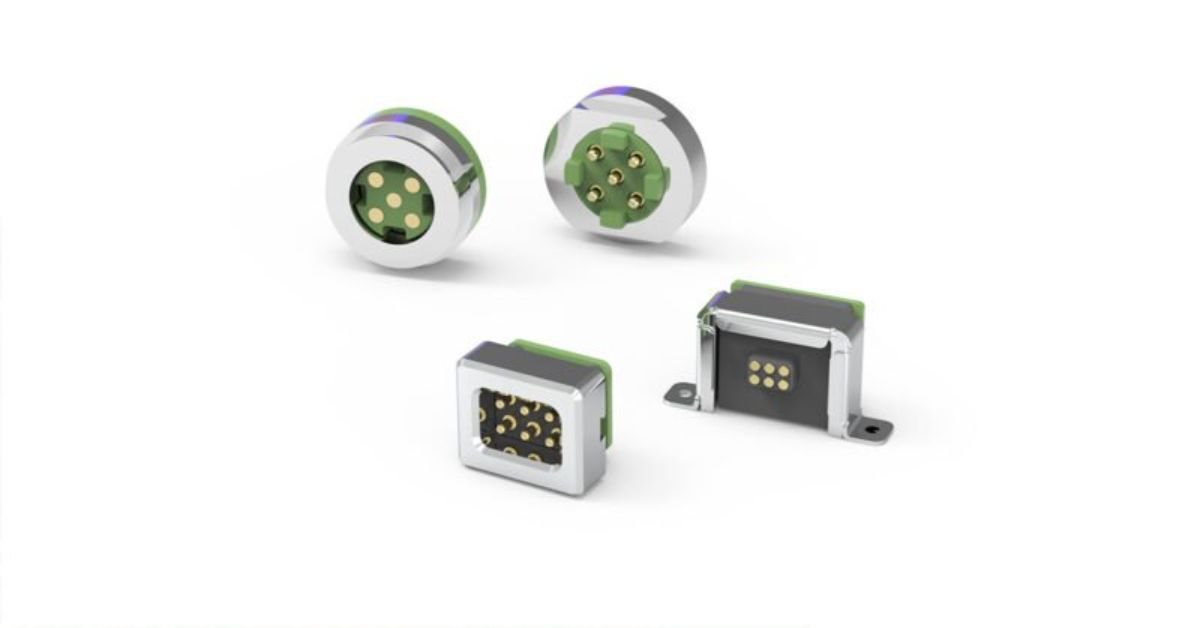
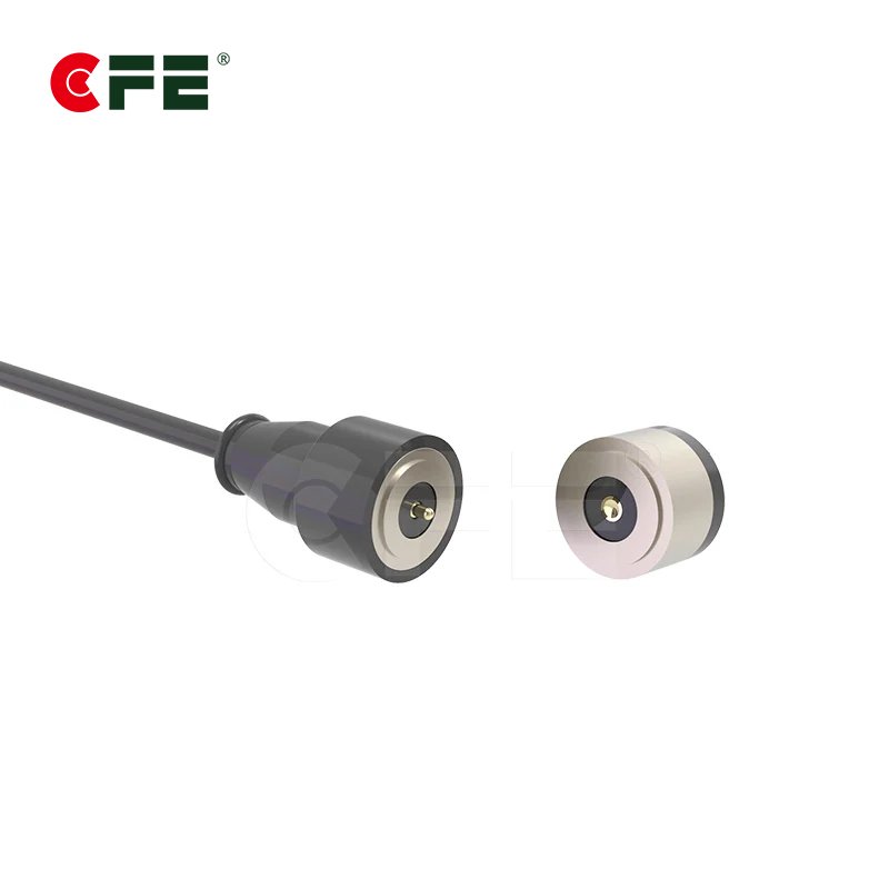
It matters most for custom work. A catalog part comes with a history of use. A custom pogo pin connector or magnetic connector does not, so your own samples are the only evidence you will have before committing to volume. Skipping or rushing this stage rarely saves time. It just moves the discovery to a more expensive moment.
Here is how the stages usually line up:
| Stage | What happens | What you walk away with |
|---|---|---|
| 1. Requirements brief | Electrical, mechanical and environmental needs are written down | A shared spec both sides can check |
| 2. CAD and drawings | Design is modeled and made buildable | 3D model plus a dimensioned drawing |
| 3. Feasibility and quote | Engineering reviews manufacturability and cost | Quotation and confirmed drawings |
| 4. Sample build | Parts are made and inspected | Physical samples |
| 5. Testing | You validate in your own product | Pass or fail evidence |
| 6. First article approval | Sample and drawing are confirmed | Signed baseline for production |
Step 1: Write the Requirements Brief Before Any CAD Exists
The most common reason a prototype round fails is not a bad design. It is a thin brief. When the supplier has to guess the current, the mating cycles or the environment, they guess, and you receive samples built for a product you are not making.
Before anyone opens a CAD tool, write down the following. CFE’s own custom pogo pin connector process asks customers for the same core items, because they speed up the whole project:
- Current and voltage: continuous and peak, per contact.
- Impedance or contact resistance: the limit your circuit can tolerate.
- Size and envelope: maximum footprint, height and keep-out zones.
- Connection mode: SMT, DIP, solder cup, wire or cable.
- Durability: how many mating cycles over the product’s life.
- Environment: water, dust, sweat, temperature, vibration.
- System application: what the connector actually does inside your device.
If you have an existing product sample or a rough idea of how the function should work, include that too. A photo of the enclosure often answers ten questions at once. And be honest about the unknowns. “We have not decided on IP rating yet” is far more useful to an engineer than a confident number you later change.
Step 2: Turn the Brief Into CAD a Factory Can Actually Build
A connector model that renders beautifully is not automatically a connector that machines, plates and assembles well. This is where design for manufacturability earns its keep.
Share a 3D file and a 2D drawing, not just one. The model shows the geometry. The drawing carries the tolerances, datums and notes that decide whether a part is acceptable. Then check a handful of things that trip up first-time designs:
- Working stroke versus full stroke. Leave margin so the spring never bottoms out in normal use. Contacts that run at the very end of travel wear faster.
- Tolerance stack-up. Add up PCB thickness, solder height, housing tolerance and mating-part tolerance. A design that works at nominal can fail at the extremes.
- Footprint and pad layout. The land pattern drives solder quality. Our guide to pogo pin solder joint inspection for OEM production explains what inspectors look for, and it is worth reading before you finalize pads.
- Lateral alignment. Pogo pins forgive a little misalignment. They do not forgive a lot. Guide features or magnets should do the aligning, not the contacts.
Picture a hypothetical wearable team that designs a dock with the pins centered on the pad at nominal. In testing, a small amount of side play in the case pushes the pins toward the pad edge and contact resistance spikes. Nothing is wrong with the connector. The tolerance stack was never checked. A ten-minute review on paper would have caught it.
Step 3: Choose the Connector Family, Materials and Finish
With a brief and a draft model in hand, you can match the need to a connector family. There is no universal best, only a best fit for your current, space and environment.
| If you need… | Consider… | Watch out for |
|---|---|---|
| Compact board-to-board or board-to-module contact | Custom pogo pin connector | Stroke, pitch and footprint tolerances |
| Blind-mating and self-alignment for charging | Magnetic connector | Retention force and polarity |
| Higher current per contact | 5A–30A high current pogo pin | Heat, copper and cable sizing |
| Exposure to water or dust | Waterproof pogo pin and magnetic connectors, 5A–30A | Seal design and mating surface |

Materials and finish deserve their own decision, not a default. Plating thickness affects wear and corrosion resistance. Housing material affects heat tolerance during reflow and long-term stability. Two articles help here: pogo pin contact pad finishes, ENIG vs. hard gold for the mating surface, and pogo pin housing materials, LCP vs. high-temp PA for the plastic around the pins.
If your project needs more than a connector, such as a connector with cable and housing, ask about a complete assembly. CFE also offers a customized module route, which can reduce the number of parts you have to coordinate yourself.
Step 4: Feasibility Review, Quotation and the Sample Build
Once the brief and drawings are in, the project moves into engineering review. At CFE this follows a defined path. The request goes to the R&D team for a manufacturing feasibility assessment, the team estimates cost from your technical requirements, and the business side issues a quotation. After the quotation is agreed and the design drawings are confirmed, a development contract is signed and, once the deposit is paid, sample production begins.
That sequence can feel slow if you are used to catalog ordering, but it is protecting you. Feasibility review is the point where an engineer can say, “This stroke will not survive 50,000 cycles, can we shorten the travel?” It is far better to hear that now.
During the sample build, raw materials are checked against the bill of materials, parts are machined and assembled, and production and finished samples are monitored by quality control before packing and shipment. For you, the practical takeaways are simple:
- Confirm which dimensions and properties will be inspected on the samples.
- Ask for the revision number of the drawing the samples were built to.
- Request packaging that matches how you will handle parts, for example tape-and-reel style packaging if you plan automated assembly.
Do not underestimate the last point. A prototype that works by hand and fails on a pick-and-place line is still a failed prototype.
Step 5: Test the Prototype Like It Will Be Abused
Samples arrive. Now comes the part that justifies the whole exercise. Test in the product, not only on the bench, and test beyond the happy path. Users will mate the connector crooked, wet and in a hurry.
| Test | What it reveals |
|---|---|
| Contact resistance, new and after cycling | Whether the interface stays stable as it wears |
| Temperature rise at rated current | Heat problems in the contact, trace or cable |
| Mating cycle test | Spring fatigue and plating wear |
| Retention and misalignment test | Whether it holds, and releases, as intended |
| Water and dust exposure | Seal and corrosion performance |
| Reflow and solder inspection | Assembly yield on your own line |
For environmental claims, agree on a recognized yardstick instead of loose wording like “waterproof.” The International Electrotechnical Commission’s IP code guidance explains how ingress protection ratings are defined, so both sides mean the same thing by the same rating.

Magnetic designs need two extra checks. First, retention force: too weak and the device drops out of the dock, too strong and users struggle to separate it. Our magnetic connector retention force design guide goes deeper. Second, polarity, because a prototype that mates the wrong way round can damage a circuit, as covered in magnetic connector polarity and preventing reverse mating. For multi-contact designs, also review how to prevent short circuits in multi-pin connectors.
One safety note: connectors carrying high current or charging a battery sit inside a bigger system. Passing your prototype tests does not replace the safety and regulatory evaluation your finished product needs for its market.
Step 6: From Approved Sample to First Article
A first article is the first unit built with production-intent parts, tooling and processes, then measured against the approved drawing and specification. The prototype proves the idea works. The first article proves the factory can repeat it.
The two are easy to confuse because both are “samples.” The difference is the process behind them. Prototype parts may be built with flexible, hands-on methods. A first article should reflect how the part will actually be made in volume. If the two differ, you are approving something you will not receive.
In CFE’s workflow, the customer receives the sample, tests it, and once it is confirmed OK, signs back the sample and drawing or an acknowledgement. Mass production then follows the agreed processes and passes quality testing before storage and shipment. That signed confirmation is your baseline, so treat it seriously.
A practical first article checklist:
- Dimensions measured against the drawing, with results recorded.
- Materials and plating confirmed against the specification.
- Electrical values checked, including contact resistance.
- Drawing revision and part number written on the approval record.
- Any deviation, however small, documented and accepted or rejected in writing.

Common Prototyping Mistakes, and How to Avoid Them
After a few rounds, patterns show up. Most delays trace back to the same handful of habits.
- Changing the spec mid-build. Every late change restarts feasibility. Freeze the brief before the quote.
- Testing only on the bench. Real enclosures, real PCBs and real hands expose problems bench rigs hide.
- Ordering too few samples. Destructive and cycle testing consume parts. Plan for them.
- Ignoring assembly. A connector must survive your reflow profile and your line, not just the lab.
- Vague approval. “Looks fine” is not a baseline. Record the drawing revision and measured results.
- Treating the first article as a formality. It is your last cheap chance to catch a gap between sample and production.
Notice what these have in common. None is a technology problem. They are communication and discipline problems, which is good news, because both are fixable with a clear checklist.
Conclusion
Good custom connector prototyping is less about speed and more about order. Write the brief. Build CAD that a factory can make. Choose the family, materials and finish on purpose. Test the samples under realistic stress. Then lock in a first article tied to a specific drawing revision. Do those things in sequence and the move to mass production becomes routine instead of risky.
If you are designing for wet, dusty or high-current conditions, start with the waterproof pogo pin and magnetic connectors, 5A–30A page to see what range is available. When you have a drawing or even a rough requirement list, you can get a quote and samples and talk through feasibility with the CFE team.
Frequently Asked Questions
What information do I need before requesting a custom connector prototype?
At minimum, provide current and voltage, size limits, connection mode, expected mating cycles, the operating environment and what the connector does in your system. A 3D model and a dimensioned drawing speed up feasibility review. If you have a sample of your product or a similar part, include that as well.
What is the difference between a prototype and a first article?
A prototype shows that a design concept works. A first article is the first unit built with production-intent parts and processes, then measured against the approved drawing. The prototype validates the idea; the first article confirms the factory can reproduce it consistently.
How many samples should I test?
Enough to cover both normal and destructive tests, with spares. Cycle, environmental and misalignment tests consume parts, so ordering the bare minimum often forces a second round. Agree on the quantity with your supplier during the quotation step.
Should I test prototypes inside my product or on a bench?
Both. Bench tests give clean electrical and mechanical data. Tests inside the real product reveal tolerance stack-up, alignment, heat and handling issues that a fixture cannot reproduce. Product-level testing is where many hidden problems appear.
Can a prototype pass and the first article still fail?
Yes, if the prototype was made with different methods, materials or tolerances than production will use. Review the process differences before approval, and record the drawing revision so any deviation is visible and documented.