Every connector looks reliable on the first mating cycle. The real test comes at cycle ten thousand, when a charging dock has been used daily for years or a test fixture has clamped its hundredth thousand board. That is where the choice between a pogo pin and a ZIF connector stops being a catalog decision and becomes a field-failure decision.
Both technologies connect to a flat pad or flex circuit, so they often end up on the same shortlist. They solve very different problems, though. This guide compares them on the points B2B buyers and design engineers care about most: cycle life, current, vibration tolerance, assembly and total cost, so you can choose with data instead of habit.
Short answer: which one wins for high-cycle use?
For high-cycle use, a pogo pin connector wins. Datasheets for ZIF (zero insertion force) connectors typically rate about 20 to 30 mating cycles, while precision spring-loaded pogo pins are commonly rated from 10,000 to 1,000,000 cycles. A ZIF connector is still the better fit for a flex cable that is assembled once and rarely disturbed.
Put simply, a ZIF connector is built to be closed and left alone, and a pogo pin is built to be touched again and again. If your product is docked, charged, tested or swapped repeatedly, the pogo pin is the natural architecture. If a ribbon cable links two boards inside a sealed housing, a ZIF is usually cheaper and entirely adequate.
What is a pogo pin connector?
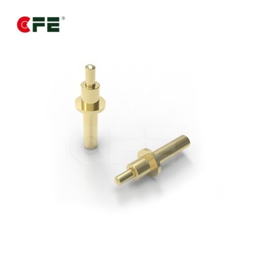
A pogo pin is a spring-loaded electrical contact made of a plunger, a barrel and an internal spring. When it meets a mating pad, the spring compresses and holds steady pressure on the contact point. That moving, self-adjusting contact is why it tolerates misalignment, height variation and repeated use so well.

Wear is shared. The plunger tip touches a gold-plated pad, the spring does the elastic work, and the barrel guides motion and carries current to the board. Because nothing relies on a plastic hinge or a locking tab, the usual fatigue points of a latched connector simply do not exist. Contact quality then depends on plating, spring force and pad design.
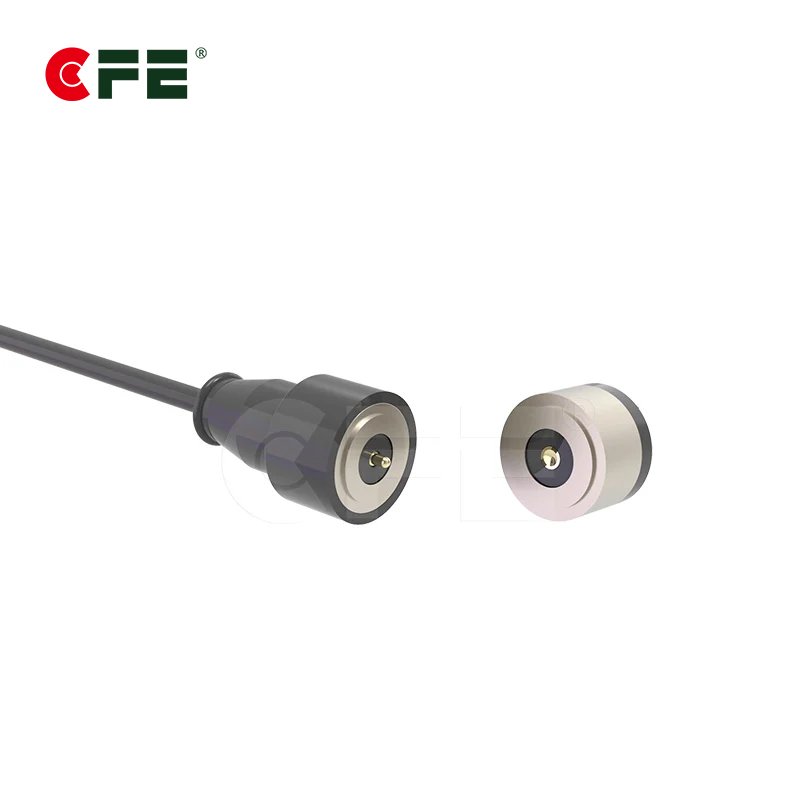
The family is broad: SMT and through-hole versions, right-angle and double-head pins, solder-cup and threaded types, and high-current variants. Pins can also be loaded into housings as arrays, or paired with magnets for blind, self-aligning docking. You can browse the full range on our pogo pin connectors page, or read our primer on magnetic connectors if you want self-alignment in the same package.


What is a ZIF connector?
A ZIF (zero insertion force) connector is a board-mounted socket that accepts a flat flexible cable (FFC) or flexible printed circuit (FPC) with no pressure while it is inserted. A flip-lock or slider actuator is opened, the flex is placed in, and closing the actuator presses the contacts onto the conductors.
The design exists for a good reason. Pushing a delicate flex cable into a tight socket by force would scuff its pads and crease the film. Removing that insertion force protects the cable and allows very fine pitch, which is why ZIF sockets dominate cameras, displays, trackpads and other compact consumer devices.
But the mechanism is also the limit. The actuator is a small plastic part that opens and closes on a hinge, and the cable itself is a consumable element. Manufacturers know this, and ZIF datasheets describe the connector as suited to a modest number of mating cycles. As an example, Amphenol’s F31S series lists durability of 30 mating cycles.
Cycle life: the numbers behind the decision
This is where the two technologies separate most clearly. Rated cycles describe how many times a connector can be mated and unmated while still meeting its electrical specification, and the gap between these two families spans several orders of magnitude.
| Connector type | Typical rated cycles | Source type |
|---|---|---|
| ZIF / FPC connector | About 20 to 30 | Amphenol and Würth Elektronik datasheets |
| Standard pogo pin connector | 10,000 and above | CFE product specifications |
| High-life pogo pin | Up to 1,000,000 | CFE life testing; Mill-Max documentation |
Read these figures with care. A rating is a laboratory result under defined force, speed and alignment, not a promise for every environment. Dust, side loading and thin plating all reduce real-world life. Still, even a conservative derating leaves pogo pins hundreds of times ahead, and that margin is what makes daily-use products possible.
Current and contact resistance
ZIF connectors are signal devices. Datasheets for common FPC families list current ratings of roughly 0.2 to 0.5 A per contact, which suits data lines, display buses and sensors. Push a ZIF toward power delivery and you meet heat, voltage drop and contact limits fast.
Pogo pins cover a much wider range. Mill-Max, for example, rates standard spring-loaded contacts between 2 and 9 A continuous with typical contact resistance near 20 mΩ at mid-stroke. Our own range includes high-current pogo pins from 5A to 30A for charging and power transfer, and one of our 2.54 mm spring-loaded parts lists a maximum contact resistance of 50 mΩ.

Two practical notes follow. First, contact resistance is mostly a plating and force story: gold over nickel on both plunger and pad keeps it stable, while worn or contaminated surfaces let it drift. Second, current rating depends on temperature rise, so check the derating curve, not just the headline amp figure. If a design needs both power and signal in one interface, a multi-pin pogo array does it without a second connector.
Vibration, shock and misalignment
Real products get dropped, carried and shaken. A ZIF connector relies on a closed actuator and the friction between flex and contacts to stay seated. Datasheets include retention force and vibration tests, yet a cable that creeps or an actuator that pops open is a classic field complaint after rough handling.
A pogo pin handles motion differently. Its spring keeps pushing the plunger onto the pad, so small shifts, thermal expansion and stack-up tolerances are absorbed instead of broken. Mill-Max, for instance, describes its spring-loaded pins as tested to a minimum of 50 g shock and 10 g vibration while maintaining continuity. The principle is general: stroke is tolerance.

Where this matters most
- Wearables and earbud cases: small parts docked daily, often with slight misalignment.
- Charging cradles and docks: repeated blind mating by users who do not line things up carefully.
- Test fixtures and ICT: hundreds of thousands of board contacts a year.
- Industrial handhelds: drops, vibration and sealed housings.
For a deeper look at one of these cases, see our guide to pogo pin connectors for TWS earbuds and wearables.
Space, assembly and total cost
ZIF wins on a few real fronts. A low-profile FPC socket can be well under two millimeters tall, and the flex cable replaces wiring, bending around corners in ways a rigid pin cannot. Per-unit pricing is low at volume, and pick-and-place assembly is mature.
Pogo pins also reflow, and SMT pins ship on tape and reel, but they require a thoughtful mating surface. You design the pad, the travel and the alignment features. That is a one-time engineering cost, and it buys you freedom to separate the two halves of the product entirely: no cable, no hinge, no tab to break.
Total cost is where high-cycle products swing. A connector that fails after a few dozen cycles generates returns, service visits and warranty claims. A slightly more expensive pin that lasts the product’s whole life usually wins once those costs are counted, which is why buyers should compare cost per cycle and cost per failure, not just unit price.
When a ZIF connector is still the right call
Pogo pins are not always the answer. A ZIF connector is a sound choice when the cable is installed during assembly and stays connected, when you need very fine pitch with dozens of signal lines, or when the flex is already part of the board-to-board design. Inside many phones and laptops, that is exactly the situation.
It also makes sense when the cable is serviced rarely, such as a replaceable display ribbon opened a handful of times in the product’s life. Twenty to thirty cycles is plenty for that. The mistake is not choosing ZIF. The mistake is using one at a user-facing interface that people will touch daily.
A selection checklist for business buyers
Before you lock a connector, answer these questions with your engineering team:
- How often will it be mated? Multiply daily use by product life. If the result exceeds a few dozen, move away from ZIF.
- Who mates it? End users create misalignment and contamination that engineers never see.
- How much current flows? Above roughly 0.5 A per contact, plan on pogo pins.
- What does the environment look like? Moisture, dust and vibration favor a sealed pogo design with a proper housing.
- What are the tolerances? Spring travel gives you room; a clamped flex does not.
- What is the cost of failure? Include returns and service, not just the part price.
Ask every supplier for the test conditions behind a cycle rating, not just the number. Plating thickness, spring force and the mating pad all change the result.
How CFE approaches high-cycle pogo pin design
CFE manufactures precision spring-loaded contacts and connectors for demanding applications. Our standard parts exceed 10,000 mating cycles, with high-life designs tested up to 1,000,000 cycles. We run our production under ISO 9001, supply RoHS and REACH compliant parts, and perform electrical testing on every unit before shipment.

For custom programs, we adapt pin geometry, spring force, plating and housing to your application, from single pins to multi-pin arrays and magnetic assemblies. If you are weighing a flex connector against a docking interface, start with our pogo pin range and send us your cycle, current and space targets so we can suggest a fit.

Conclusion
The comparison is less a contest than a question of role. ZIF connectors are efficient, dense and economical for flex cables that are connected once. Pogo pins are durable, tolerant and capable of real current for interfaces that are used again and again. For high-cycle use, the gap is not subtle: tens of cycles against tens of thousands or more.
Decide by counting actual mating events, adding the cost of failure, and testing a real sample in your own assembly. That small amount of discipline up front is cheaper than any redesign later.
Frequently asked questions
Is a pogo pin better than a ZIF connector?
For repeated mating, yes. Pogo pins are typically rated from 10,000 to 1,000,000 cycles, while ZIF connectors list roughly 20 to 30. ZIF remains better for compact, fine-pitch flex cables that are installed once and left in place.
How many mating cycles does a ZIF connector last?
Most ZIF and FPC connector datasheets rate between 20 and 30 cycles, though ratings vary by series and manufacturer. The actuator hinge and the cable pads usually wear first, so check the specific datasheet for your part.
Can a pogo pin carry more current than a ZIF connector?
Yes. ZIF contacts are generally rated for about 0.2 to 0.5 A each, while pogo pins range from around 2 A to 9 A for standard designs and up to 30 A for specialized high-current types. Always confirm the rating at your allowed temperature rise.
Do pogo pins work in vibration and misaligned designs?
They do. The spring keeps contact force on the pad while absorbing movement, tolerance stack-up and slight misalignment. Good design still needs a well-plated mating pad and mechanical guides, particularly in products that are docked blindly by users.
Can I replace a ZIF connector with a pogo pin connector?
Often, when the interface is user-facing or frequently mated. It is a redesign rather than a drop-in swap, because you need mating pads, travel and alignment features on the opposite side. Send your requirements to our team and we can review the options.
Have a high-cycle interface to design? Explore our pogo pin connectors or email cfe@cfeconn.com with your cycle, current and space requirements.
References: Amphenol F31S Series datasheet; Mill-Max, Introduction to Spring-Loaded Pogo Pins and Connectors; Digi-Key, The Basics of Pogo Pin Connectors.