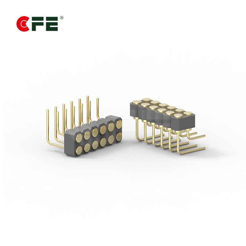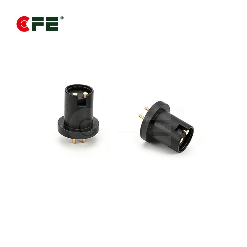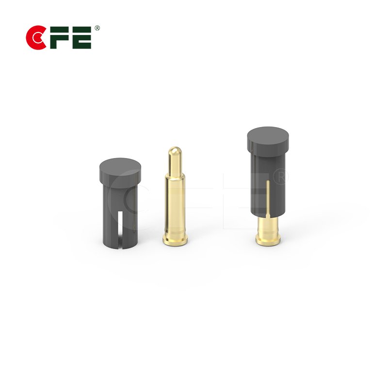
If your product needs to push more than a few hundred milliamps through a spring-loaded contact, picking the wrong pogo pin isn’t a minor spec miss — it’s a heat problem, a reliability problem, and eventually a warranty problem. High-current pogo pins in the 5A–30A range are doing real work: charging robotics, powering docking stations, and feeding handheld POS terminals through thousands of mating cycles. Get the selection wrong and you’ll see discoloration, spring fatigue, or worse — a melted connector housing during a live demo.
This guide walks through exactly what to check before you commit to a high-current pogo pin design, and where CFE’s own product line fits into that decision.

What Makes a Pogo Pin “High-Current” in the First Place?
Not every spring-loaded pin is built for power delivery. Most pogo pins in consumer electronics — the ones inside earbuds, smartwatches, or Bluetooth trackers — are signal-and-light-charging pins, typically rated well under 3A. A high-current pogo pin is a different animal: larger pin diameter, heavier internal spring, and a plating stack chosen to survive sustained I²R heating rather than just low-voltage signal transfer.
The practical dividing line most engineers use is this: if your application needs to move usable charging current — not just data or a trickle charge — you’re in high-current territory, and the pin has to be engineered for it from the ground up rather than pushed past its comfortable rating.
Why the Current Rating Is the Whole Ballgame
Contact Resistance and Heat Generation
Every pogo pin has some contact resistance, and under Joule heating that resistance turns directly into heat: power dissipated at the contact rises with the square of the current. Push 10A through a pin engineered for 3A and the temperature rise at the contact point can climb well past what the housing material or plating can tolerate. Industry testing on power connectors generally targets keeping that temperature rise to around 30°C above ambient before performance and safety start to degrade — and pogo pins follow the same physics as any other spring contact.
This is exactly the derating problem covered well in this connector derating explainer, which is worth a read if you’re specifying pins for a design that runs hot or sits in an enclosed housing with limited airflow.
Spring Force and Material Composition
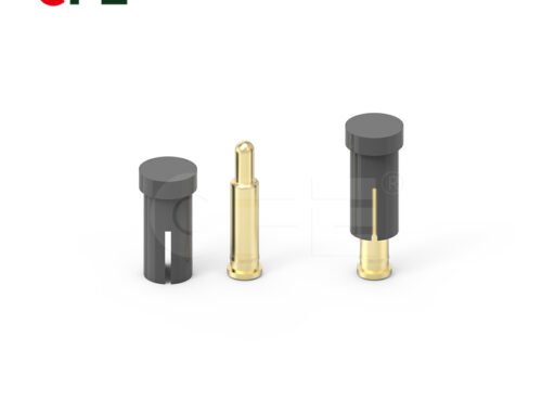
Current-carrying capacity isn’t only about the pin’s diameter — it’s also about how consistently the spring maintains contact pressure over the life of the product. A weak or fatigued spring increases contact resistance over time, even if the pin was correctly rated on day one. That’s why high-current pogo pins typically use a heavier gauge stainless steel or beryllium copper spring, sized to hold reliable contact force across tens of thousands of mating cycles rather than just at first use.
Key Factors When Selecting a 5A–30A Pogo Pin
Pin Diameter and Contact Area
Larger diameter pins carry more current comfortably because they offer more cross-sectional area and more surface contact at the tip. As a rough guide:
| Pin Diameter | Typical Current Range | Common Use Case |
|---|---|---|
| ø1.0–1.5mm | 1A–3A | Wearables, TWS earbuds, signal contacts |
| ø2.0–3.0mm | 3A–10A | Handheld devices, POS terminals, docking stations |
| ø3.5mm and above | 10A–30A | Robotics, battery packs, industrial charging systems |
These are starting points, not guarantees — the final rating always depends on plating, spring force, and duty cycle together, not diameter alone.
Plating: Gold vs. Other Finishes
Gold plating over nickel is the default choice for a reason: it resists oxidation, keeps contact resistance low and stable over time, and holds up under repeated mating cycles better than bare copper or tin finishes. For higher-current pins specifically, plating thickness matters more than it does for signal pins — a thin flash gold layer that’s fine for 1A can wear through faster under the higher mechanical and thermal stress of a 20A application, exposing the base metal underneath and causing contact resistance to climb.
Spring Design and Travel Distance
Travel distance (the distance the pin compresses) affects how forgiving the connector is to mechanical tolerance stack-up in the mating housing. For high-current applications where the connector may see repeated docking — a robot returning to a charging station, or a POS terminal being placed back in its cradle dozens of times a day — a longer travel spring with a well-controlled force curve keeps contact pressure consistent even as tolerances shift slightly over the product’s lifetime.
Housing Material and Insulation
At higher currents, the housing isn’t just a mechanical holder — it’s part of the thermal and safety picture. High-temperature engineering plastics (like LCP or high-temp nylon) are standard for high-current pogo pin housings because they need to tolerate sustained heat near the contact without softening, deforming, or compromising the insulation between adjacent pins.
Matching Current Ratings to Real-World Applications
Robotics and Charging Docks
Humanoid and service robots typically return to a dock to recharge large battery packs, and that charging current is often well beyond what a consumer wearable pin could safely handle. Robotics charging contacts commonly sit in the 10A–30A range, with housings designed to survive frequent, sometimes imprecise docking.

POS Terminals and Handheld Devices
Handheld point-of-sale terminals and payment devices need enough current to charge a battery quickly between shifts while also, in many designs, transmitting data through the same docking interface. This dual role means the pogo pins in a POS charging cradle are frequently spec’d toward the middle of the high-current range — enough to charge fast, without the oversized housing that pure 30A industrial connectors would require.

By contrast, if you’re designing wearables or TWS earbuds rather than a high-power dock, the pin selection criteria shift considerably — we cover that lower-current side of the spectrum in our companion post on pogo pin connectors in TWS earbuds and wearables.
Certification and Quality Standards to Check
Current rating on a datasheet only means something if it’s backed by real testing. Before committing to a supplier for a high-current pogo pin design, confirm they can show:
- RoHS and REACH compliance documentation for the materials used
- ISO-certified manufacturing quality management
- Temperature-rise test data at the actual current your design requires, not just a headline “rated current” number
- Mating-cycle durability data relevant to your product’s expected dock/undock frequency

Quick gut check: if a supplier can’t show you temperature-rise data at your actual operating current — not just a generic “rated up to X amps” line — treat that number as unverified.
Common Mistakes When Choosing High-Current Pogo Pins
- Sizing to peak current only. Sustained current matters more than a brief peak — a pin that survives a 2-second inrush spike can still overheat under continuous load.
- Ignoring duty cycle. A pin docked once a day sees very different thermal and mechanical stress than one cycling hundreds of times daily.
- Treating all gold plating as equal. Plating thickness and underlying nickel barrier quality vary significantly between suppliers, even when both list “gold plated” on the datasheet.
- Skipping real thermal testing. Simulation and datasheet math are a starting point, not a substitute for testing the pin in your actual housing and airflow conditions.
How CFE Engineers High-Current Pogo Pin Solutions
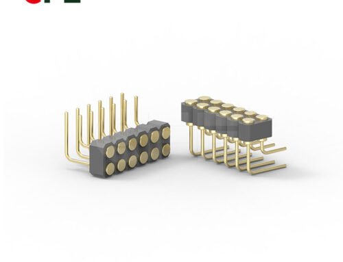
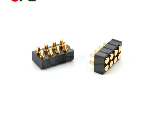
CFE builds pogo pin connectors specifically for the 5A–30A range used in robotics, POS terminals, and industrial charging equipment, with plating thickness, spring force, and housing material selected around the target current rather than adapted from a lower-power signal pin design. Every high-current line is backed by RoHS, REACH, and ISO documentation, and CFE supports custom pin diameter, travel distance, and housing configurations for teams that need something outside a standard catalog part.
If you’re specifying connectors for a new design, our pogo pin connector product line covers the standard and custom configurations available for high-current applications, along with technical drawings and current-rating data for each series.
Conclusion
Choosing a high-current pogo pin comes down to matching four things to your real operating conditions: pin diameter, plating quality, spring design, and housing material — then verifying all four with actual test data rather than a headline current rating. Get that match right and a well-specified 5A–30A pogo pin will outlast the product it’s built into. Get it wrong, and the failure usually shows up exactly where you can least afford it: mid-charge, in the field, after the warranty conversation has already started.
Frequently Asked Questions
Can a single pogo pin actually carry 30A safely?
Yes, but only with a large enough pin diameter, a heavy-duty spring, and a housing rated for the resulting heat — and only when backed by temperature-rise testing at that specific current, not just a datasheet maximum.
Do high-current pogo pins need more maintenance than standard pins?
Not typically, provided the initial spec was correct. Properly rated high-current pins are designed for the same thousands-of-cycles durability as standard pogo pins; problems usually trace back to undersizing at the design stage rather than ongoing wear.
Is gold plating necessary for high-current applications, or can I use a cheaper finish?
Gold over nickel is strongly recommended for anything beyond low-cycle prototypes. Cheaper finishes tend to oxidize faster, which raises contact resistance over time — and rising resistance under high current means rising heat.
How do I know if my application needs 10A or 30A pins?
Start from your battery’s actual charge current requirement and add margin for inrush and duty cycle, then work with your connector supplier to confirm the pin diameter and spring design that comfortably covers that number with room to spare — not right at the edge of the rated maximum.
Can CFE customize pin diameter or travel distance for a specific high-current design?
Yes — CFE supports custom pin diameter, spring travel, and housing configurations for high-current projects that fall outside standard catalog specifications.