A practical comparison for engineers choosing between spring-loaded pogo pins and rigid pin headers for internal PCB connections.

Every compact electronic device — from a smartwatch to a warehouse scanner — relies on more than one PCB working together. Getting signal, power, and ground from one board to another sounds simple, but the connector you choose for that job quietly determines how reliable, repairable, and space-efficient your final product will be. For decades, pin headers and sockets were the default answer. Today, spring-loaded pogo pin connectors are replacing them in a growing number of designs, and the reasons go far beyond trend-chasing.
This article breaks down how pogo pins and traditional header connectors actually work, where each one holds up under real-world stress, and the specific situations where switching to pogo pins measurably improves your product. If you’re specifying a board-to-board connector for your next design, the comparison below will help you make that call with confidence.
What Is a Board-to-Board Connector?
A board-to-board (B2B) connector physically and electrically joins two PCBs so current and data signals can pass between them without a cable harness. It might stack one board directly above another, mate two boards at a right angle, or bridge a small daughterboard to a main board inside a sealed enclosure. The connector has to hold mechanical alignment, maintain low contact resistance over the product’s lifetime, and often survive repeated mating cycles during assembly, testing, or field service.
How Traditional Header Connectors Work
Traditional pin headers use a rigid male pin that inserts into a female socket housing. Contact is made through friction — the pin is slightly oversized relative to the socket’s spring contact, so it’s held in place by mechanical tension. This design has served the industry well for a long time because it’s inexpensive, widely available, and easy to source in almost any pitch.
But rigid headers have real limitations:
- No tolerance for misalignment. Because both the pin and socket are rigid, even a small manufacturing tolerance stack-up or board warp can cause poor contact or bent pins.
- Wear from repeated mating. Friction-fit contacts degrade after a limited number of insertion cycles, which is a problem for products that get disassembled for service or testing.
- Vulnerable to vibration and shock. In handheld or wearable devices, constant micro-movement can loosen a friction-fit connection over time, leading to intermittent signal loss.
- Bulkier profile. Socket housings add height and footprint that many slim, modern devices simply can’t spare.
How Pogo Pin Connectors Work
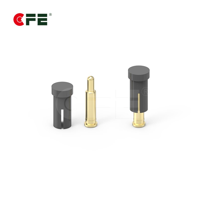
A pogo pin connector uses a spring-loaded plunger inside a barrel, pressing against a flat or slightly concave pad (a “target”) on the mating board. Instead of relying on friction between two rigid parts, the spring itself supplies constant, consistent contact force — regardless of minor board flex, thermal expansion, or vibration.
That single design difference is what gives pogo pins their advantage in demanding applications:
- Consistent contact force. The internal spring keeps pushing against the target even as the boards shift slightly, so the connection stays stable under vibration and shock.
- High mating cycle life. Quality pogo pins are rated for tens of thousands to over a million mating cycles, far outperforming friction-fit headers in devices that connect and disconnect often.
- Tolerance for misalignment. Because the target pad doesn’t need to precisely capture a rigid pin, pogo connectors are more forgiving of minor board stack-up variation.
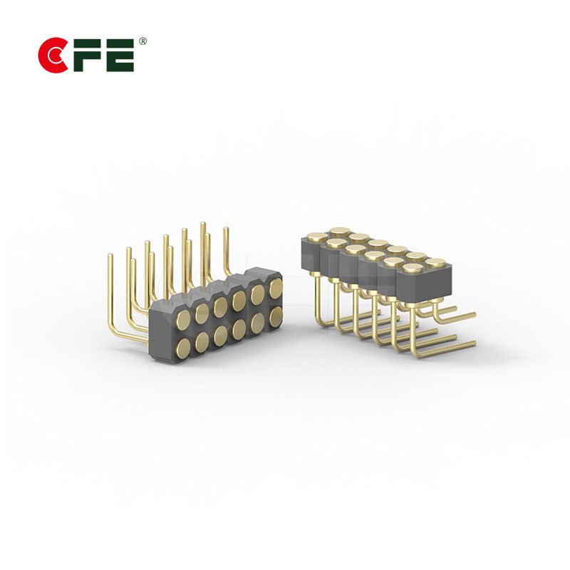
- Lower profile options. SMT and right-angle pogo pin packages let designers hit very tight z-height and footprint targets that traditional header-and-socket pairs can’t match.
- Easier field serviceability. Pogo-to-pad connections make disassembly and reassembly during testing or repair far less risky for the contact itself.

Pogo Pins vs. Traditional Headers: A Direct Comparison
| Factor | Traditional Header | Pogo Pin Connector |
|---|---|---|
| Contact mechanism | Friction fit | Spring-loaded constant force |
| Vibration resistance | Moderate | High |
| Mating cycle life | Thousands | Tens of thousands to 1,000,000+ |
| Misalignment tolerance | Low | Higher |
| Footprint / height | Larger (needs socket housing) | Compact (SMT, right-angle, DIP options) |
| Field serviceability | Risk of bent pins | Low risk, pad-based contact |
| Best for | Static, low-cycle internal connections | Wearables, docking, testing, modular assemblies |
When Pogo Pins Are the Clear Winner
Pogo pins don’t replace headers in every design — for a permanent, low-vibration internal connection that’s assembled once and never touched again, a standard header can still be the most cost-effective choice. But in several categories, pogo pins are now the default engineering choice:
Wearables and Smart Devices
Smartwatches, fitness bands, and AI glasses pack multiple boards into a tiny, curved enclosure that flexes slightly with wear. A right-angle or SMT pogo pin connector handles that movement without losing signal integrity, which is exactly why so many wearable charging and board-to-board interfaces use exposed pogo contacts.

True Wireless Earbuds (TWS)
The charging case-to-earbud interface is one of the highest-cycle connections in consumer electronics, mated and unmated dozens of times a day. Pogo pins are essentially the industry standard here because they tolerate the constant micro-misalignment of a pocket-sized docking mechanism.
POS Terminals and Handheld Scanners
Devices that dock into a charging cradle hundreds of times a shift need a connector that won’t wear out or need pin-straightening. Right-angle and high-current pogo pin connectors are built for exactly this kind of repeated, high-cycle contact.
Robotics and Modular Hardware
Robotic arms, sensor modules, and swappable hardware blocks benefit from pogo pins’ ability to maintain contact through vibration and repeated module swaps.
Test and Programming Fixtures
Any board-to-board interface used for functional test or in-circuit programming needs to survive thousands of touchdowns without contact degradation — a job traditional headers were never designed for.

Design Considerations When Specifying Pogo Pin Connectors
Switching from headers to pogo pins isn’t just a drop-in swap — a few design details matter:
- Mounting style. SMT pogo pins suit automated, high-density assembly; through-hole (DIP) styles give a more mechanically robust connection for boards under more physical stress; right-angle versions solve tight z-height or edge-mounted layouts.
- Current rating. Standard pogo pins typically handle a few amps, but high-current variants are available for power delivery paths — match the pin’s rated current to your actual load, not just your signal pins.
- Pin plating. Gold-plated contacts resist oxidation and keep contact resistance low across the connector’s rated cycle life — don’t substitute cheaper plating on a connector that will see frequent mating.
- Pitch and stroke. Tighter pitches suit dense, small-footprint boards, while stroke length (the plunger’s travel distance) needs to match your enclosure tolerance stack-up.
- Custom configurations. Many designs benefit from a custom pin count, housing shape, or waterproof sealing rather than forcing a standard part into a non-standard layout.
CFE’s board-to-board pogo pin connector range covers SMT, DIP, right-angle, high-current, and solder-cup configurations, along with custom design support for teams that need a connector built around their exact board layout rather than the other way around.
Why Manufacturers Are Standardizing on Pogo Pins
Beyond the raw performance numbers, there’s a practical manufacturing argument for pogo pin connectors. Precision-turned pogo pins don’t require injection-molded housings or stamped socket bodies, which means shorter tooling lead times for custom pin counts and layouts. For teams iterating on a wearable or IoT product where the board layout might change between prototype revisions, that flexibility can shave real time off a development cycle. It’s part of why organizations like the IPC and broader electronics manufacturing community have documented pogo pin adoption growing steadily across consumer, industrial, and test-equipment segments over the past decade.
FAQs
Q1: Are pogo pin connectors more expensive than traditional headers?
Per-unit cost can be slightly higher for pogo pins, but the total cost of ownership often favors pogo pins in high-cycle applications, since you avoid warranty returns from bent pins or worn-out friction contacts.
Q2: Can pogo pin connectors handle high current, like battery charging?
Yes. High-current pogo pin connectors are specifically designed for power delivery, with larger pin diameters and plating optimized for lower contact resistance under sustained load.
Q3: How many mating cycles can a pogo pin connector survive?
It depends on the design, but quality pogo pin connectors are commonly rated from 10,000 up to over 1,000,000 cycles — far beyond what a friction-fit header is built for.
Q4: Are pogo pins waterproof?
Standard pogo pin connectors are not inherently waterproof, but sealed and waterproof pogo pin variants exist for outdoor, wearable, and IP-rated enclosure applications.
Q5: Can I get a custom pogo pin connector for my board layout?
Yes — pin count, pitch, stroke length, housing shape, and plating can all be customized to match a specific PCB layout rather than forcing your design around a standard part.
Conclusion
Traditional header connectors still have their place in static, low-cycle, cost-sensitive designs. But once a product needs to survive vibration, frequent docking, or tight tolerance stack-ups — wearables, TWS earbuds, POS cradles, robotics, or test fixtures — pogo pin connectors consistently outperform them on durability, contact reliability, and footprint. If your next board-to-board connection needs to hold up under real-world use rather than just a lab bench test, it’s worth specifying a spring-loaded pogo pin connector from the start rather than retrofitting one later. Explore CFE’s full pogo pin connector lineup to find the mounting style, current rating, and configuration that fits your design.