
Multi-pin Pogo Pin connectors are a core component in precision interconnection systems. By combining individual Pogo Pins with a plastic insulating holder, they enable parallel multi-channel signal or power transmission within highly compact spaces. This article provides a professional breakdown of their architecture, design advantages, selection criteria, and industry applications.
1. What Is a Multi-Pin Pogo Pin Connector?
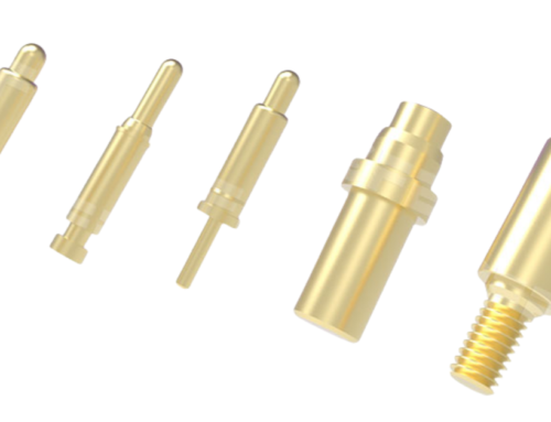
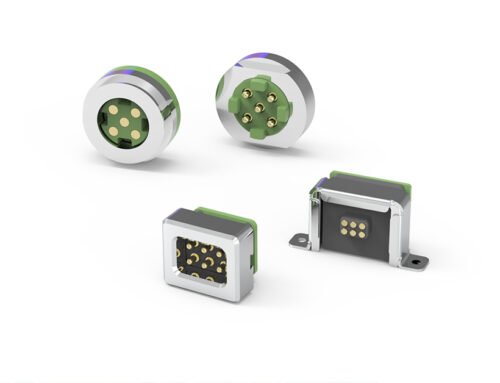
A multi-pin Pogo Pin connector is a precision interconnect device that enables pluggable connections between printed circuit boards (PCBs) using spring-loaded probes. The fundamental building block is the individual Pogo Pin—a crimped assembly consisting of a plunger (pin head), a spring, and a barrel (tube). Multiple Pogo Pins are then inserted into a plastic insulating housing at precise spacing (pitch) to form a multi-pin array. This modular design allows multiple signal or power lines to be connected in parallel within a limited PCB footprint. Standard configurations range from 2 pins to 128 pins, accommodating a wide spectrum of design requirements.

2. Core Component Breakdown: From Single Pin to Multi-Pin Array
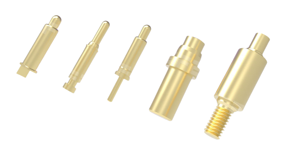
2.1 Plunger
The plunger is the direct point of contact with the mating surface (e.g., PCB pads or battery terminals) and serves as the entry point for current and signal transmission.
- Materials: Typically beryllium copper (BeCu) or stainless steel (SK), with a gold-plated surface to enhance conductivity and wear resistance.
- Tip Geometries: Depending on the application, common plunger tip designs include:
- Sloped (chisel) tip
- Sloped tip with ball
- Through-hole integrated design
- Back-drilled structure
2.2 Spring
The spring provides the necessary extension force and contact pressure for reliable mating.
- Materials: Usually stainless steel (SUS304) or music wire, selected for excellent fatigue resistance.
- Force Design: Single-pin contact force is typically controlled within 50–100 gf. This range ensures low contact resistance while preventing excessive stress that could damage mating components. Precise spring parameter control is critical for achieving consistent performance and long-term reliability across different use cases.
2.3 Barrel
The barrel houses both the spring and the plunger, serving as the probe’s primary conductive path and structural backbone.
- Materials: Phosphor bronze or stainless steel, with a nickel underplate followed by gold plating to improve conductivity and corrosion resistance.
- Tail Termination Styles: To accommodate various soldering methods, barrel tails are available in multiple configurations:
- SMT
- Through-hole
- Solder cup
- Right-angle

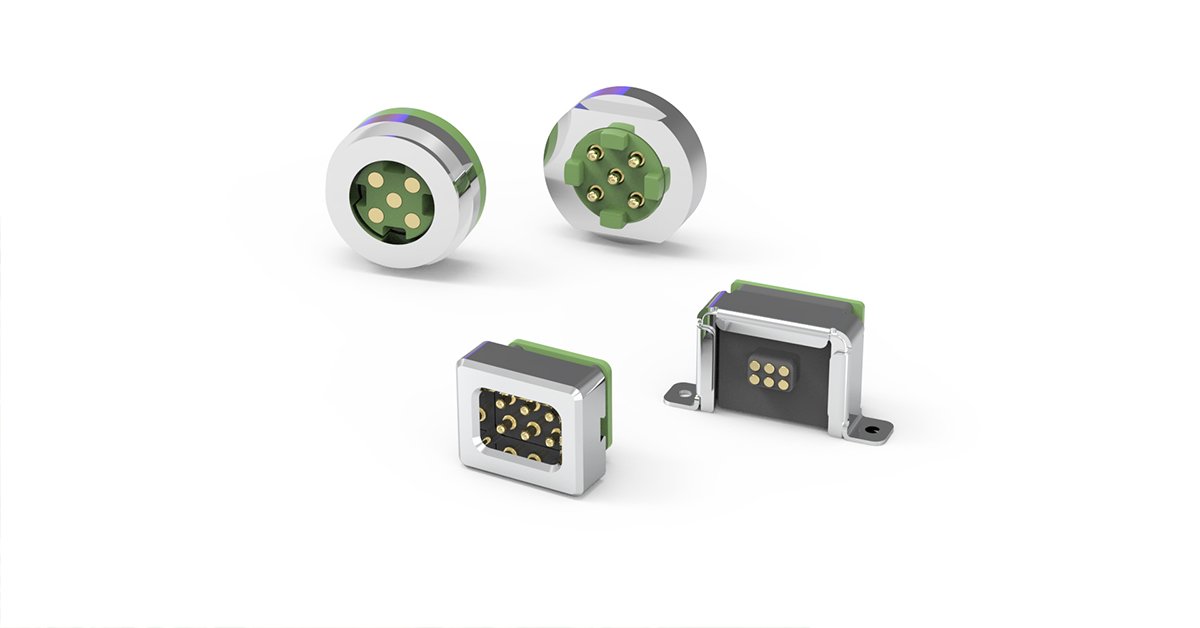
2.4 Plastic Insulating Housing
Multiple Pogo Pins are securely positioned and insulated by a plastic holder, which also provides alignment and protection.
- Materials: High-temperature engineering plastics such as LCP and HTN are commonly used, supporting single-row, dual-row, and male/female mating configurations. This housing enables the creation of robust, modular multi-pin assemblies.
3. How to Select the Right Multi-Pin Pogo Pin Connector
3.1 Standard Selection Guide
CFE offers a comprehensive range of standardized multi-pin connectors to meet diverse design needs, with flexible options for pin count, pitch, and form factor. Key parameters to consider include:
| Pitch | Pin range | Layout |
|---|---|---|
| 1.27mm | 2~30Pin | Single/double row |
| 2.0mm | 2~72Pin | Single/double row |
| 2.54mm | 2~128Pin | Single/double row |
| 3.0mm | 2~48Pin | Single/double row |
3.2 Industry Application Solutions
Pogo Pin connectors have become the interconnection backbone across numerous sectors:
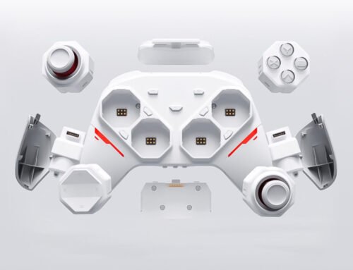
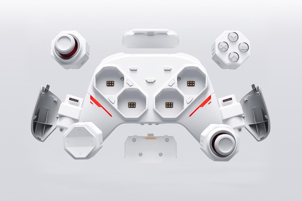
- Consumer Electronics: AI smart glasses, AR/VR headsets, TWS earbuds, smartwatches, active styluses, e-cigarettes
- Automotive Electronics: Intelligent cockpits, onboard charging guns, sensors, cigarette lighters
- Medical Devices: Body temperature monitors, ECG monitors, blood glucose meters, beauty devices
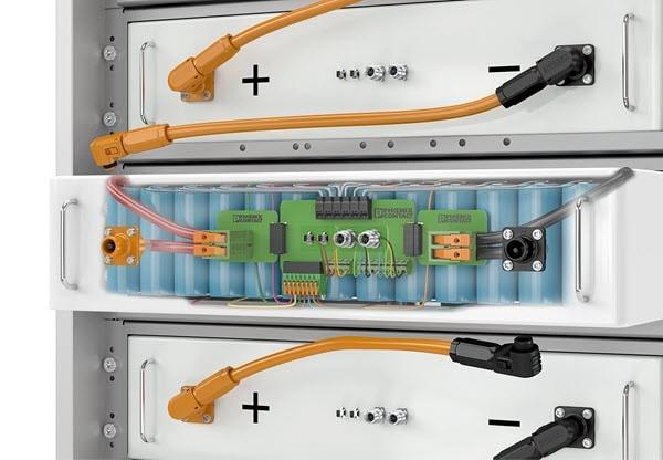
- Industrial & Communications: Robotics, 5G antennas, data centers, GPS trackers, energy storage cabinets
- LED Lighting: Shelf lighting, LED display panels, track spotlights, display case lighting
4. FAQ
Q1: What is the difference between a single-pin and a multi-pin Pogo Pin connector?
A: A single-pin Pogo Pin is used for point-to-point connections. A multi-pin connector integrates multiple Pogo Pins into a plastic housing at defined pitches, enabling simultaneous parallel transmission of multiple signals or power lines—ideal for complex, modular circuit designs.
Q2: Does CFE support custom multi-pin connector designs?
A: Yes. CFE offers full customization services covering pin count, pitch, arrangement, tail termination, and even full module integration. Each design is tailored to the customer’s mechanical constraints, power requirements, and application environment.
Q3: How is contact reliability ensured in multi-pin connectors?
A: Reliability is driven by precision engineering. CFE employs sloped plunger designs that ensure 100% wall-contact between the plunger and barrel inner wall—current travels along the barrel wall rather than through the spring, ensuring stable low-impedance transmission. Combined with precisely controlled spring force and high-quality gold plating, this guarantees long insertion/withdrawal cycle life and consistent electrical performance.