If you have ever tried to fit one more contact onto a shrinking PCB, or watched a charging pin arc and overheat under load, you already understand why pogo pin pitch is one of the most important — and most overlooked — decisions in connector design. Pitch, the center-to-center distance between adjacent pins, quietly controls how small your device can be, how much current it can carry, how reliably it can be assembled, and how much your connector will cost per unit.
At CFE Connector, we design and manufacture pogo pin connectors for wearables, 5G equipment, medical devices, POS terminals, and industrial robotics, and pitch selection is one of the first questions every engineer asks us. This guide walks through what pitch actually means, the standard sizes available, and the five factors that should drive your decision — so you can spec a connector that fits, performs, and survives production.
What Is Pogo Pin Pitch, and Why Does It Matter?
Pitch is measured from the center of one pin to the center of the neighboring pin, in a single row or between rows on a multi-row array. It sounds like a simple geometric spec, but it is really a proxy for several engineering constraints at once:
- Board real estate — tighter pitch packs more contacts into less space.
- Current capacity — smaller pitch usually means a thinner pin barrel and plunger, which limits how many amps a single contact can safely carry.
- Manufacturing tolerance — fine-pitch arrays demand tighter plating, drilling, and placement tolerances, which affects yield and cost.
- Mechanical reliability — wider pitch generally tolerates more misalignment and mechanical shock before a contact drops out.
Get the pitch wrong and you either waste board space with an oversized connector, or you choose something so fine that assembly yields drop and unit cost climbs. Getting it right the first time saves a redesign cycle later.

Standard Pogo Pin Pitch Sizes You Should Know
Most pogo pin connectors are built around a handful of industry-standard pitches, which keeps tooling costs down and lets you source from multiple qualified vendors. The most common sizes are:
| Pitch | Typical Use Case |
|---|---|
| 2.54 mm (0.1″) | General-purpose headers, test fixtures, industrial equipment |
| 2.0 mm | Compact consumer electronics, docking stations |
| 1.5 mm | Charging cradles, small appliances |
| 1.27 mm (0.05″) | Wearables, handheld devices, medical peripherals |
| 1.0 mm | Smartwatches, fitness trackers, AR/VR headsets |
| 0.8 mm and below | TWS earbuds, smart rings, ultra-compact wearables |
Below roughly 0.8 mm, pitch enters “fine-pitch” territory. At this scale, pick-and-place placement accuracy, solder mask registration, and plating consistency all become critical, and not every manufacturer can hold the tolerances needed for a reliable, high-cycle-life connection.
5 Factors That Determine the Right Pitch for Your Design
1. Device Size and Miniaturization Needs
This is usually the starting constraint. A smartwatch, hearing aid, or true wireless earbud case has very little edge space to work with, which pushes designers toward 1.0 mm, 0.8 mm, or finer pitches. Larger products — POS terminals, robotics joints, industrial docking systems — have more room to work with and can use 2.0 mm or 2.54 mm pitch, which is cheaper to manufacture and easier to hand-solder for prototyping or repair.

2. Current and Power Requirements
Pitch and current capacity are directly linked because pitch limits how large the pin barrel and plunger can physically be. A fine-pitch 0.8 mm pin might safely carry a few hundred milliamps, while a wide-pitch, large-barrel pin can be rated for 3 A, 5 A, or even up to 30 A in high-current designs. If your product needs to fast-charge a battery or deliver meaningful power through the connector, don’t choose pitch based on space alone — check the current rating of the pin family first, then confirm it fits your layout.

3. Pin Count and Circuit Density
If your interface needs many signal lines — power, ground, data, and several sense or ID lines — a finer pitch lets you fit them all into a small footprint. But every additional pin at a tighter pitch increases the risk of solder bridging and cross-talk. It is often better to combine a moderate pitch with a two-row or staggered layout than to force everything into a single ultra-fine-pitch row.
4. Mounting Method and Manufacturing Tolerances
The way the connector is mounted — SMT (surface mount), DIP (through-hole), solder cup, or right-angle — interacts with pitch to determine how forgiving your assembly process will be. SMT reflow assembly can handle finer pitches consistently because placement is automated, while hand-soldered solder-cup or DIP connectors are easier to work with at 2.0 mm pitch or wider. If your production line relies on manual assembly or field repair, avoid specifying a pitch finer than your process can reliably support.
5. Application Environment and Durability
Devices that face frequent docking cycles, vibration, or outdoor use benefit from a wider pitch and larger contact area, which tolerates more mechanical misalignment before a connection drops. Sealed, waterproof designs also need enough physical space around each pin for gasketing, which can rule out the finest pitches even if the board layout would otherwise allow them.
Matching Pitch to Real-World Applications
A quick reference for how pitch typically plays out across common product categories:
- TWS earbuds and hearables: 0.8 mm or finer, low current, SMT mounted, very tight tolerance.
- Smartwatches and fitness trackers: 1.0–1.27 mm, moderate current for charging, SMT mounted.
- POS terminals and payment devices: 1.27–2.0 mm, balances density with rugged daily docking cycles.
- Robotics and industrial equipment: 2.0–2.54 mm or custom wide pitch, prioritizes current capacity and mechanical durability over miniaturization.
- High-current charging docks: wide, custom pitch built around large-barrel, high-amperage pins rather than a standard grid.

Why Custom Pitch Pogo Pins Make Sense
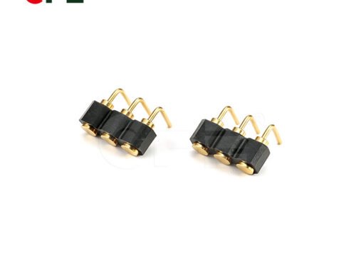
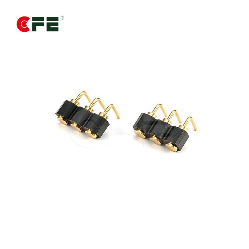
Standard pitches cover most designs, but plenty of products — especially in wearables, 5G hardware, and specialized medical devices — need a pitch, pin count, or row spacing that doesn’t exist off the shelf. Working with a manufacturer that can design a fully custom array, rather than adapting an existing catalog part, means your pitch is chosen to fit the product instead of the other way around. CFE Connector’s pogo pin connector line includes SMT, DIP, solder cup, right-angle, and high-current styles, and our engineering team can develop a custom pitch and layout around your board outline, current budget, and cycle-life target.
Common Pitch Selection Mistakes to Avoid
- Choosing pitch before confirming current needs — a beautifully compact layout is useless if the pins can’t carry the required amperage.
- Ignoring assembly capability — specifying 0.5 mm pitch for a line that hand-solders prototypes will slow you down and hurt yield.
- Skipping mechanical tolerance stack-up — fine pitch leaves very little room for misalignment between mating connectors; always check total tolerance, not just nominal pitch.
- Assuming smaller is always better — the “best” pitch is the widest one that still meets your size constraint, not the smallest one available.
Frequently Asked Questions
What is the most common pogo pin pitch?
2.54 mm (0.1 inch) and 1.27 mm (0.05 inch) are the most widely used pitches because they align with standard header and connector footprints, keeping tooling and sourcing costs low.
Can pogo pin pitch affect current rating?
Yes. Finer pitch limits the physical size of the pin barrel and plunger, which caps the safe current per contact. Wide-pitch, large-barrel pins can handle several amps or more, while fine-pitch pins are typically rated for signal-level or low-power currents.
What pitch is used for wearable devices like smartwatches or earbuds?
Most wearables use 1.0 mm to 1.27 mm pitch, and ultra-compact products like true wireless earbud cases often go down to 0.8 mm or finer to fit within the available space.
Is a smaller pitch always better for miniaturized products?
Not necessarily. Smaller pitch supports miniaturization, but it also tightens manufacturing tolerances, can lower current capacity, and may increase per-unit cost. The right pitch balances size against current, reliability, and assembly capability.
Can I get a custom pogo pin pitch instead of a standard size?
Yes. Manufacturers with in-house tooling and design engineering, such as CFE Connector, can develop a custom pitch, pin count, and row spacing tailored to your board layout and performance requirements rather than limiting you to catalog sizes.
Conclusion
Pitch is not just a spacing number on a datasheet — it is a decision that ripples through your product’s size, power delivery, assembly process, and long-term reliability. Start by confirming your current and pin-count requirements, check what your assembly line can realistically support, and only then optimize for the smallest pitch that still meets those constraints. When a standard size doesn’t fit your design, a custom pitch built specifically for your application is usually a better long-term choice than forcing a catalog part to work.
Ready to specify the right pogo pin connector for your product? Explore CFE Connector’s full range of pogo pin connectors, including SMT, DIP, solder cup, right-angle, and high-current options, or reach out to our engineering team for a custom pitch design.