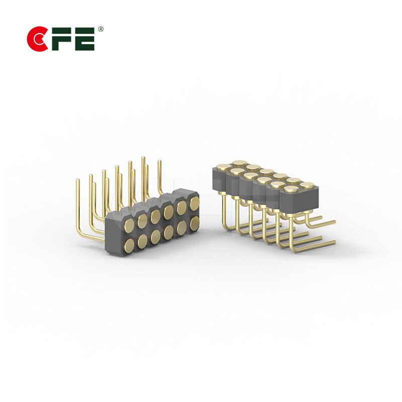
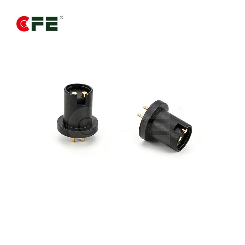
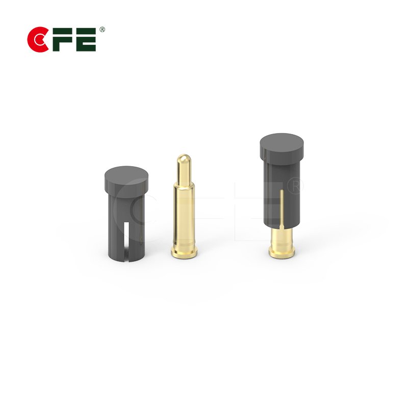
As electronic devices continue to evolve toward miniaturization and higher integration, connector reliability directly impacts overall system performance and user experience. Spring-loaded contact pins, with their unique elastic contact structure and excellent electrical transmission capabilities, have become critical interconnect components across smart wearables, medical devices, robotics, laptops, and many other industries.
This article starts with the fundamental structure of PogoPin, systematically analyzes common internal structure types, and introduces CFE’s technological breakthroughs in spring pin structural innovation.
PogoPin Basic Structure & Working Principle
A spring-loaded pogo pin consists of three precision-machined components:
- Barrel: Precision turned and formed, with the tube opening curled inward to house the plunger and spring while preventing the plunger from escaping
- Plunger: Turned and formed, with the tip serving as the contact surface and the tail end engaging with the spring, allowing axial sliding within the tube
- Spring: Provides continuous contact force, ensuring a stable, low-resistance electrical connection between the plunger and the mating surface
- Working Principle: The plunger remains in constant contact with the mating surface under spring force, while the internal retaining feature (curled tube opening) ensures the plunger moves within a specified stroke range, achieving reliable electrical continuity.

Comparison of Four Common PogoPin Internal Structures
Based on different internal tube designs, PogoPins can be categorized into four classic types:
| Structure Type | Design Feature | Advantage |
|---|---|---|
| ① Beveled Tip | Internal beveled step to retain spring and plunger | Simple structure, lower manufacturing cost |
| ② Beveled Tip with Ball | Precision ball added to the bevel; plunger rolls against the ball | Significantly reduces friction, extends mechanical life and contact stability |
| ③ Integrated Through-Hole | Through-hole design with no internal step | Simple structure, easy to clean |
| ④ Back-Drilled | Reverse drilling process creates an internal retaining step | Enables longer spring stroke in limited space, improves contact force and structural strength |

CFE Innovative Structures — Engineered for Special Applications
While standard structures meet most conventional requirements, they often have limitations when facing extreme operating conditions, harsh environments, or highly integrated products. With years of deep expertise in spring-loaded pin technology, CFE has developed dozens of new contact pin structures tailored to specific customer needs, secured by multiple invention and utility model patents.
CFE can integrate the following functional components into PogoPins for systematic performance and reliability enhancement:
| Component | Functional Value |
|---|---|
| Precision Insulator | Prevents signal crosstalk between multiple pins; ideal for high-density arrangements |
| Precision Positioning Pin / Tail Plug | Improves assembly accuracy and soldering stability |
| Precision Inner Sleeve / Outer Sleeve | Enhances structural strength for high-frequency mating scenarios |
| Precision Ball | Reduces friction and extends mechanical life |
| Precision Retaining Clip | Enables quick-lock and anti-pullout functions |
| PEEK Sleeve | High-temperature resistance and excellent insulation for harsh environments |
| Sealing Ring | Achieves IP68-rated waterproof and dustproof protection |
Why Choose CFE Spring Loaded Pogo Pin Solutions?
- Structural Design Capability: Dozens of innovative structure variants available for rapid customization across application scenarios
- Precision Manufacturing: High-accuracy turning and assembly capabilities ensure product consistency and reliability
- Patented Technology: Multiple invention and utility model patents offer differentiated technical solutions
- Full-Cycle Service: Comprehensive technical support from structural design and prototyping to volume delivery
FAQ
Q1: How many mating cycles can a PogoPin withstand?
CFE PogoPins support 10,000–100,000 mating cycles under standard test conditions. Actual life depends on structure type, plating material, and real-world usage. The beveled tip with ball structure typically delivers superior cycle life due to reduced friction.
Q2: Which of the four structures offers the lowest contact resistance?
Both the beveled tip with ball and back-drilled structures generally exhibit lower contact resistance. The ball type minimizes contact surface wear through rolling friction, while the back-drilled design provides a more stable contact force through extended spring stroke.
Q3: How do I choose the right PogoPin structure for my product?
Selection depends on mating frequency, space constraints, environmental conditions (waterproof/dustproof/temperature resistance), current/signal requirements, and budget. CFE’s technical team offers professional structure selection guidance — feel free to contact us for in-depth consultation.
Closing
Within the tiny structure of a PogoPin spring pin lies decades of evolution and refinement in connection technology. CFE continues to push the performance boundaries of spring-loaded connectors through ongoing innovation and precision manufacturing, delivering more reliable and professional interconnection solutions to customers worldwide.
For more information on PogoPin internal structure types or to discuss a custom connector solution, please reach out to the CFE technical team.