
What Is a Pogo Pin? Definition, Structure, and Working Principle
A plain-English breakdown of the small spring-loaded connector behind your smartwatch charger, your wireless earbuds case, and thousands of factory test fixtures.
If you’ve ever charged a smartwatch on a magnetic dock, tested a circuit board on a factory line, or plugged in a set of true wireless earbuds, you’ve used a pogo pin without ever seeing it. It’s a small part with an outsized job: making sure two surfaces connect electrically every single time, no matter how many times you dock, undock, or re-seat them.
For engineers sourcing connectors, or product teams trying to figure out why a competitor’s charging case feels so much more solid than theirs, understanding what a pogo pin actually is — and how it’s built — makes it much easier to choose the right one. That’s exactly what we’ll break down here.
What Is a Pogo Pin?
A pogo pin is a spring-loaded electrical connector built around a metal pin that compresses under pressure and pushes back with steady force. The name comes from the pogo stick: push down, and the internal spring resists, storing energy and maintaining constant contact pressure against whatever it’s touching.
In electronics, that “constant contact pressure” is the entire point. Rigid connectors depend on a perfect, unchanging fit. Pogo pins don’t — they’re designed to absorb small amounts of misalignment, vibration, and repeated wear while still holding a stable electrical connection. That’s why they show up in devices that get plugged, unplugged, docked, or tested over and over: chargers, test fixtures, wearables, and modular electronics.
For a closer look at how these connectors are engineered and specified for real production use, CFE Connector’s pogo pin connector solutions cover the range of configurations available for different current, durability, and space requirements.
The Structure of a Pogo Pin
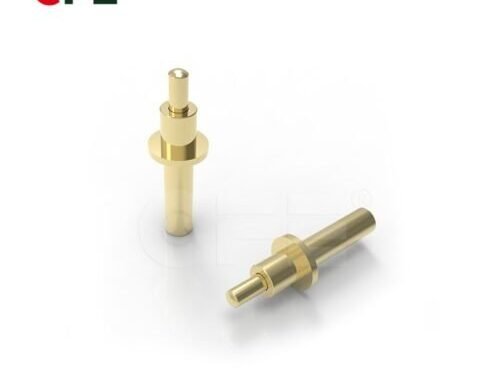
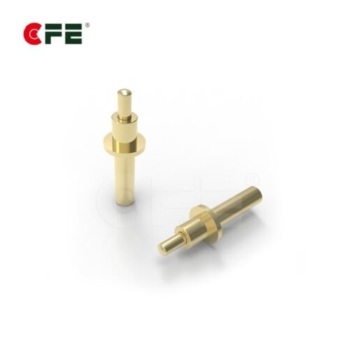
A pogo pin looks simple from the outside, but it’s really a small mechanical assembly with four core components, each doing a specific job.

Barrel
The barrel is the outer metal housing that holds everything together. It’s typically machined from brass or stainless steel and often plated with gold, nickel, or other conductive finishes to resist oxidation and reduce contact resistance. The barrel’s internal diameter and wall thickness determine how much travel and force the pin can handle without deforming.
Plunger
The plunger is the part that actually makes contact with the mating surface. It sits at the top of the barrel and moves up and down as pressure is applied. Plungers come in different tip shapes depending on what they need to touch and how much wear they need to survive.
Spring
Tucked inside the barrel, the spring is what gives the pogo pin its name and its function. It’s usually a precision-wound piece of stainless steel or beryllium copper, calibrated to deliver a specific force range (measured in grams) at a specific compression depth. Too weak, and the connection becomes unreliable under vibration. Too strong, and it wears down the mating contact or draws excess current.
Tip Style
The very end of the plunger — the point of actual contact — comes in several shapes:
- Flat tip — broad, stable contact area, good for larger pads
- Round/dome tip — self-centering, tolerant of minor misalignment
- Crown tip — multiple points of contact, useful in dusty or oxidized environments
- Sharp/pointed tip — can pierce light oxide layers or coatings for a cleaner connection
Choosing the right tip is one of the most overlooked decisions in connector design, and it has a direct effect on long-term reliability.
How Pogo Pins Work
The working principle of a pogo pin is straightforward mechanically, but it’s worth understanding because it explains why these connectors are so widely trusted in demanding applications.
- Compression. When the mating surface (a PCB pad, a charging contact, a test probe target) presses against the plunger, the plunger is pushed down into the barrel.
- Spring resistance. The internal spring compresses and pushes back with a calibrated amount of force, keeping the plunger pressed firmly against the contact surface.
- Electrical continuity. Current flows from the mating surface, through the plunger, through the spring (or a separate internal conductive path, depending on design), and out through the barrel to the connected circuit.
- Return. When pressure is released, the spring pushes the plunger back to its resting position, ready for the next connection cycle.
This cycle can typically be repeated tens of thousands to over a million times, depending on the pin’s design and materials, which is why pogo pins are the connector of choice anywhere something needs to be plugged and unplugged repeatedly rather than soldered once and left alone. For a deeper technical walkthrough of pogo pin design considerations, DigiKey’s basics of pogo pin connectors article is a solid reference.
Types of Pogo Pins and Mounting Styles
Not all pogo pins are built the same way. The right type depends heavily on the application and how it needs to attach to a board or housing.


SMT (Surface Mount) Pogo Pins
Reflow-soldered directly onto the PCB surface, SMT pogo pins keep the profile low and are well suited to compact, high-density designs like wearables and handheld devices.
DIP / Through-Hole Pogo Pins
Through-hole pins pass through plated holes in the board and are soldered on the opposite side, giving a stronger mechanical bond — useful where the connector will see repeated physical stress.


Right-Angle Pogo Pins
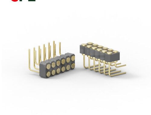
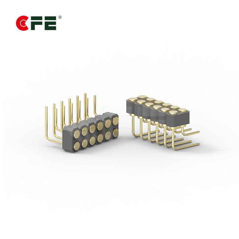
Configured at a 90° angle to the board, right-angle pins support horizontal mounting where vertical space is limited.
Magnetic Pogo Pin Connectors
A pogo pin combined with a magnet, so the two halves of a connection self-align and snap together — the design behind most smartwatch chargers and magnetic charging cables shown earlier. The magnet handles alignment; the pogo pin still does the electrical work.
Custom Multi-Pin Arrays
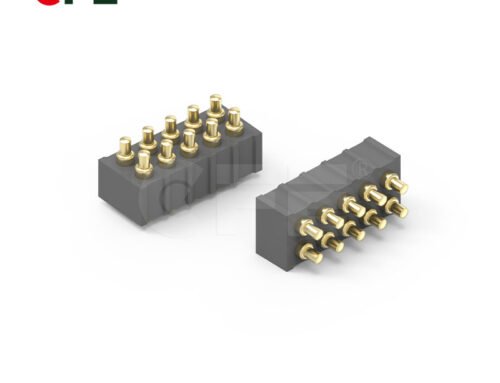
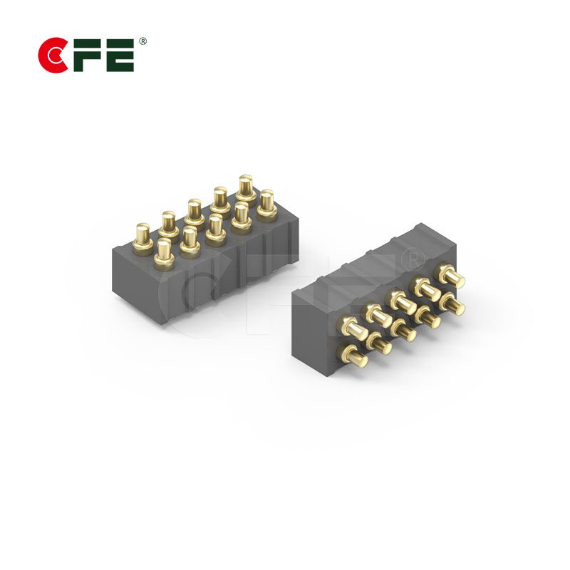
For higher pin counts or unusual layouts, pogo pins can be arranged into custom blocks and circular arrays, letting a single connector carry power, signal, and ground lines in one compact footprint.
Common Applications

Pogo pins show up in far more places than most people realize:
- Consumer electronics — charging docks, magnetic cables, smartwatches, TWS earbud charging cases, smart rings, AI glasses
- Testing and manufacturing — ICT (in-circuit test) fixtures, functional test probes, burn-in testing
- Point-of-sale and payment devices — docking stations and modular payment terminal contacts
- Medical devices — wearable monitors, docking stations for diagnostic equipment
- Industrial and robotic equipment — ruggedized connectors that survive vibration and repeated connect/disconnect cycles
In each case, the underlying need is the same: a reliable, repeatable electrical connection in a compact form factor, without the labor cost or rigidity of a soldered joint.
Why Manufacturing Precision Matters

A pogo pin’s performance comes down to tolerances measured in microns. Spring force that varies even slightly across a batch of pins can cause some connections in an array to make solid contact while others intermittently fail — a problem that’s often invisible until a product is already in the field.
This is why plating quality, spring calibration, and barrel machining tolerances matter as much as the basic pin design. Two pogo pins that look identical on a datasheet can behave very differently after 50,000 insertion cycles if one was manufactured with tighter process controls than the other.
Why it matters for sourcing: Certifications like ISO and RoHS aren’t just paperwork — they reflect the process controls that keep spring force and plating thickness consistent across every batch, which is exactly what prevents intermittent field failures.
Choosing the Right Pogo Pin for Your Product
A few practical questions to work through when specifying pogo pins for a design:
- What current does the connection need to carry? This affects barrel diameter and plating.
- How many insertion cycles is the connector expected to survive? This determines spring material and tip hardness.
- What’s the available space? Pin pitch and overall height need to fit the enclosure design.
- Will the connection be exposed to moisture, dust, or vibration? This affects tip style and sealing requirements.
- Is self-alignment needed? If so, a magnetic pogo pin connector may simplify the mechanical design significantly.
CFE Connector’s team works through exactly these variables when specifying pogo pin and magnetic connector solutions for client products, matching pin design to the electrical and mechanical demands of the application rather than defaulting to a generic off-the-shelf part.
Need a pogo pin connector built to spec?
CFE Connector designs and manufactures custom pogo pin and magnetic connector solutions for consumer electronics, medical, and industrial applications.
Conclusion
A pogo pin is a deceptively simple component — a barrel, a plunger, a spring, and a contact tip — but that simplicity is exactly what makes it so dependable. By converting mechanical pressure into steady, repeatable electrical contact, pogo pins solve a problem that rigid connectors can’t: staying reliable through thousands of connect-and-disconnect cycles, in tight spaces, without constant maintenance. Whether it’s a wearable charger, a manufacturing test fixture, or a modular industrial connector, understanding the structure and working principle behind pogo pins makes it much easier to specify the right one — and to avoid the subtle manufacturing shortcuts that cause field failures down the line.
Frequently Asked Questions
What’s the difference between a pogo pin and a regular connector pin?
A regular pin makes contact through a fixed, rigid fit. A pogo pin uses an internal spring to maintain constant contact pressure even when there’s slight movement or misalignment, making it far more tolerant of repeated use.
How much force does a pogo pin spring typically apply?
It varies by design, but most pogo pins are calibrated to deliver anywhere from a few grams to over 100 grams of force at full compression, depending on the current-carrying and durability requirements of the application.
Can pogo pins carry high current?
Standard pogo pins are designed for low-to-moderate current (signal and low-power charging). For higher current needs, larger-diameter, heavy-duty pogo pins with thicker plating are used instead of standard signal-pitch pins.
Why do some pogo pin connections fail over time?
The most common causes are spring fatigue after excessive cycles, plating wear that increases contact resistance, or contamination (dust, oxidation) on the tip. Choosing the right tip style and plating for the environment reduces this risk significantly.
Are magnetic pogo pin connectors less reliable than standard ones?
Not inherently — the magnet only handles alignment. The electrical connection itself is still made by the pogo pin, so reliability depends on the same spring and plating quality as any other pogo pin design.