<!doctype html>
Magnetic Connector Polarity: Preventing Reverse Mating
By CFECONN | Last updated: November 1, 2026 | Reading time: about 9 minutes
Here is a scenario every hardware team dreads. A magnetic charging port passes bench testing and ships in volume. Then a field report arrives: a user flipped the cable, the halves snapped together anyway, and a charging circuit went quiet for good. Nobody was careless. The connector simply allowed a mating it should have refused.
That is reverse mating, and for B2B buyers it is one of the cheapest risks to design out and one of the costliest to discover late. This guide explains how magnetic connectors prevent it, where each method falls short, and what to put in your quote request. If your design also needs sealing and high current, start with CFE’s overview of waterproof pogo pin and magnetic connectors for 5A–30A designs.
Quick answers
- Reverse mating: joining the two halves of a connector in the wrong orientation, so power or signal contacts meet the wrong partners.
- Magnet pole coding: arranging magnets so only the correct orientation attracts and the wrong one repels.
- No single method is enough. Strong designs layer magnet coding, keying or pin layout, and electrical protection.
- Tell your supplier first whether users can flip the connector, rotate it, or both.
What Reverse Mating Is and Why B2B Buyers Should Care
A magnetic connector exists to make connecting effortless. That is also its weakness. A barrel jack or USB plug has a shape that forces one orientation. A magnetic connector, built to snap on from any angle, gives up some of that shape on purpose.
Two different mistakes hide under one name. A flip turns one half over, so positive and negative swap. A rotation turns it around a round face, so multi-pin signals land on the wrong pins. They need different fixes.
The cost grows with current. At 5A and above, reverse polarity is no longer a dimmed LED. It can mean a failed charging IC, an overheated contact or a returned unit. In a B2B program that failure repeats across every unit in the order, and a sealed product usually cannot be repaired.

Layer 1: Magnet Pole Coding
Pole coding is the signature trick of magnetic connectors. Opposite poles attract and like poles repel. If each half carries two magnets arranged as a mirrored pair, the correct orientation pulls everything into place, while a flipped half puts like poles face to face and pushes away. The user feels the part refuse to seat, and the contacts never touch.
Correct orientation: halves attract
Flipped: halves repel
N
S
S
N
N
S
N
S
Opposite poles meet: pins seat and conduct
Like poles meet: contacts stay apart
The diagram shows the idea. It works because the refusal is physical and immediate. No firmware is involved, and nothing can be skipped by a tired technician.
Pole coding has limits, and buyers should know them:
- One magnet cannot code rotation. A single central magnet on a round face attracts at any angle, so the pins must be rotationally symmetric.
- Tight pitch invites a wrong neighbor. If magnets sit too close, a magnet can be pulled toward the adjacent one and the half slides sideways. Magnet spacing is part of the design, not an afterthought.
- Magnet strength cuts both ways. Enough pull to hold, but not so much that the connector grabs debris or fights separation.
Magnet layout also shapes the field outside the connector. A pattern of alternating poles can reduce the far field, which matters when a compass or Hall sensor sits nearby. We cover that trade-off in our guide to magnet stray fields and sensor protection.
Layer 2: Mechanical Keying
Keying uses geometry: a notch, a D-shaped outline, an offset guide boss, a shoulder that only clears in one position. It is the oldest method and the most intuitive, because the user sees why the part will not fit.
In a magnetic connector, keying works best as a partner to the magnets, not a replacement. The whole appeal of the format is quick, tolerant, lateral release. A deep key can slow engagement or trap the half during a sideways pull. A shallow key paired with pole coding gives you the best of both: guidance by eye, and refusal by force.

Layer 3: Asymmetric Pin Layouts
Pin layout is the quiet protector. Take a symmetric two-pin row. Turn one half 180 degrees and the positive contact lands on the negative one. Move one pin off-center, or add an insulating land where a contact would otherwise sit, and a flipped mating finds no partner at all.
For round faces, designers often choose the opposite strategy: a concentric layout, with a center contact and an outer ring. Orientation then stops mattering by design, because every rotation makes the same connection. This suits simple power links, while multi-pin signal connectors usually need an asymmetric pattern instead.
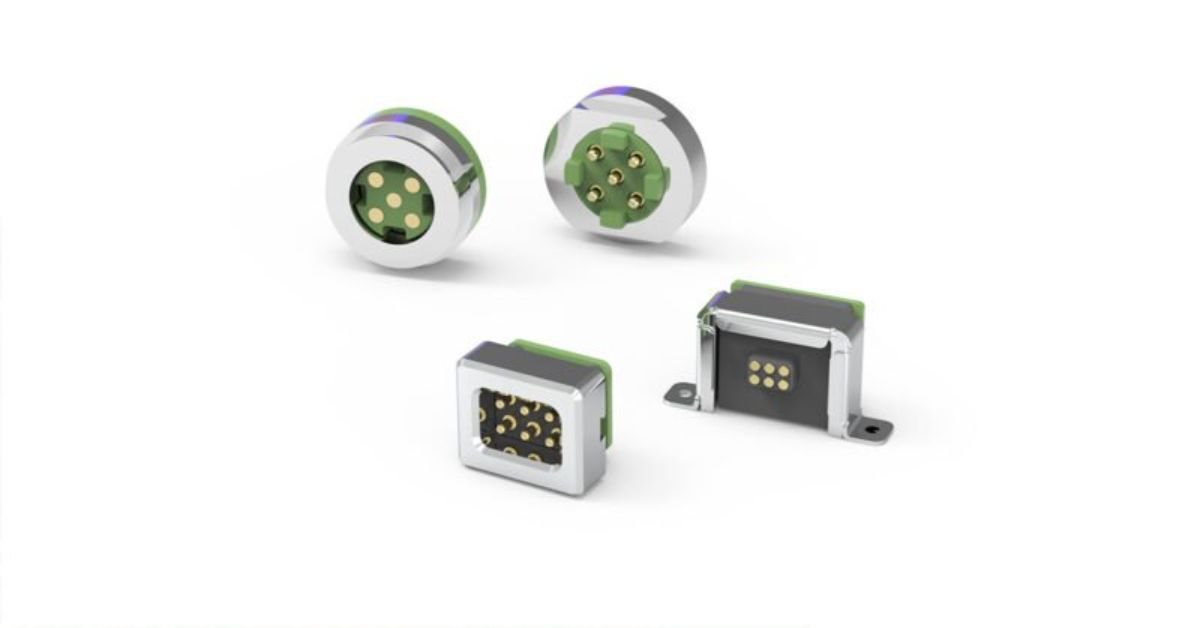
Tell your supplier which approach fits your product. If you need a pattern that does not exist yet, CFE builds from a custom pogo pin connector starting point, and the round magnetic connector family shows what is already available.
Layer 4: Electrical Protection
Mechanical and magnetic methods prevent wrong mating. Electrical protection limits the damage if one happens anyway, whether from a cable wired backwards at assembly or a worn part. Common options include:
- Series diode. Simple and cheap, but it drops voltage and burns power at high current.
- Ideal-diode MOSFET. A P-channel or controller-driven MOSFET blocks reverse current with far lower loss.
- Fuse or resettable fuse. A last line of defense against a hard short.
- Detect-before-power. The source stays off until the connection is confirmed.
Here is why this matters at high current. As a rough illustration, a diode dropping 0.4V at 10A dissipates about 4W, while a MOSFET with 10 milliohms of on-resistance dissipates about 1W at the same current. Verify the numbers against your own parts, but the pattern holds: the protection itself can become a thermal problem. Our notes on PCB design for 30A pogo pins and why four 5A pogo pins do not make a 20A connection explain the heat side in more detail.
Which Method Fits Which Job?
| Method | Stops flip | Stops rotation | Main limit |
|---|---|---|---|
| Magnet pole coding | Yes | Only with 2+ magnets | Pitch and strength must be tuned |
| Mechanical keying | Yes | Yes | Can slow engagement or trap the half |
| Asymmetric pin layout | Yes | Yes | Needs custom pin pattern |
| Electrical protection | Limits damage | Limits damage | Adds loss, cost and heat |
For most B2B products we would suggest at least two layers: magnets plus either pin layout or electronics. For medical or safety-critical uses, plan on three, and review the medical connection solutions page for typical requirements.
Wet, Dirty and High-Current Conditions Change the Answer
Polarity protection that works on a clean bench can behave differently in the field. Water is the main reason. Powered contacts exposed to moisture corrode faster, and a half-seated or wrongly seated connector keeps a live path open exactly where you do not want it. Our explanation of why powered pogo pin contacts corrode in water shows how quickly this develops.
Three practical rules follow. Keep the powered side recessed or inert until a valid connection is made. Check that a half-seated connector cannot conduct. And confirm the sealing method on the waterproof pogo pin or magnetic part you choose, because “waterproof” should come with a stated test, not just a word. The IP code system in IEC 60529 is the usual language for that conversation.
High current adds another rule: cable and contact choice must keep pace with the protection scheme. See our AWG versus mm² guide and the 5–30A magnetic connector range when sizing a power path.

A Worked Example: The MXA-0010
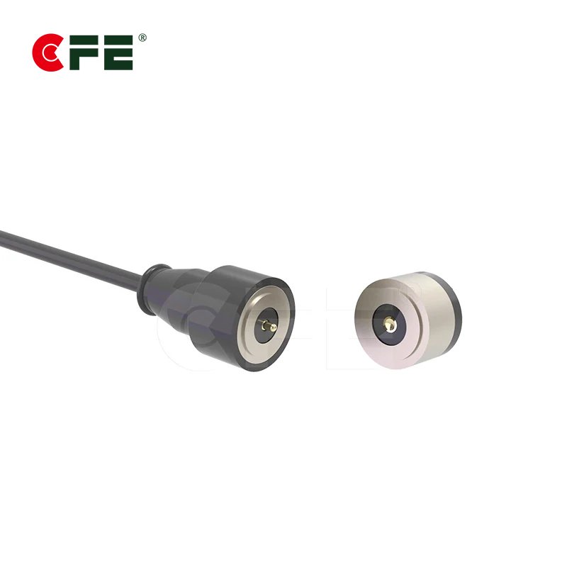
CFE’s MXA-0010 2-pin magnetic DC power connector is a useful reference point. Its product page lists a rated 12V, 5A, a magnetic force of 4.6N, NdFeB permanent magnets, a 20,000-cycle life test and a maximum contact resistance of 50 milliohms. The description says magnet positioning and a dual circuit protection structure are used to distinguish direction.
That is a clear statement of intent, though the page does not publish the exact coding scheme. If your design depends on how a specific part rejects a flipped mating, ask CFE engineering for the drawing and test method. It is a normal request, and it saves a prototype round.
The wider background is on the record: CFE was founded in 2009, has customized magnetic connectors since 2011, and states it has covered nearly 800 products across more than 200 fields. See the company profile and quality page to check those claims.
Reverse-Mating Checklist for Your Quote Request
A supplier can only protect against a failure it knows about. Many requests list current and pin count, then stop. Add the rows below.
| What to send | Why it matters |
|---|---|
| Can the user flip it, rotate it, or both? | Decides magnet, key and pin pattern |
| Current, voltage and pin count | Sets the pin series and protection load |
| Available space and pitch | Limits magnet spacing and keying depth |
| Wet, dusty or outdoor use | Drives sealing and corrosion plan |
| Sensors or cards nearby | Sets stray-field limits |
| Cycle-life target | Checks magnet and contact wear |
| Pass criterion for wrong mating | Defines the reverse-mating test |
Then agree on the test. Try to force the wrong orientation at several angles and offsets, with a current-limited supply, and require no conduction in any wrong position. Repeat after cycle testing and under wet conditions. Our guide to testing a waterproof pogo pin connector covers the sealing side.
Talk to the CFE Engineering Team
If reverse mating is a risk in your product, raise it before tooling. Browse the 5–30A magnetic connectors, the magnetic cable range or the waterproof 5A–30A landing page, then send your requirements through the quote and samples form or email cfe@cfeconn.com. CFE is also exhibiting at Electronica in Munich, November 10–13, 2026, Booth B2.540. Details are on the exhibition invitation page.
Conclusion
Reverse mating is not one problem but two, flip and rotation, and no single fix covers both. Magnet pole coding refuses a flipped part by force. Keying and pin layout guide the user. Electronics catch what slips through. Pick at least two layers, state your pass criterion, and test the wrong orientation as seriously as the right one. If you are unsure which layers your product needs, bring the drawing to the CFE team early; a short review before tooling costs far less than a redesign after launch.
Frequently Asked Questions
What is reverse mating in a magnetic connector?
Reverse mating means the two halves are joined in the wrong orientation, either flipped 180 degrees or rotated to the wrong position. Power and signal contacts then meet the wrong partners, which can damage circuits or simply leave the device dead.
Can magnets alone prevent reverse polarity?
Magnets can stop a flipped connection, because like poles repel. They do not stop every error, such as rotation on a round face, or a cable wired the wrong way at the factory. Good designs add keying, pin layout or electrical protection on top.
Do waterproof magnetic connectors need extra polarity protection?
Often yes. Water on powered contacts speeds corrosion, so a wrong or half-seated mating in a wet setting does more harm. Ask for a design where the powered side stays dead until a valid connection is made.
How do I test a connector for reverse mating?
Try to force the wrong orientation by hand and by fixture, at several angles and offsets, with a current-limited supply. Pass means no conduction in any wrong position. Repeat after your full cycle-life test and under wet conditions.
What should I send CFE for a polarity-coded custom connector?
Send the current, voltage, pin count and pitch, whether users can flip or rotate the part, the space available, the environment, and your cycle target. Add any magnetically sensitive parts nearby so magnet layout can be planned once.