It looks like simple arithmetic. Four pins, five amps each, twenty amps in total. A sourcing sheet will happily let you write that down. The physics will not let you keep it.
If you are buying or specifying pogo pins for a charger, battery pack, or power module, this one assumption causes more field failures than almost any other. This guide explains why it breaks, shows the numbers, and gives you a practical way to specify a real 20A connection.
Why don’t four 5A pogo pins make a 20A connection? Because current never splits evenly across parallel pins. A 5A rating is a heat limit for one pin, and when one pin touches late or lifts, the others carry more than their share and overheat. A four-pin set is only safe at 20A if every pin makes perfect contact on every mating cycle, and real assemblies cannot promise that. Use a pin rated for the full current, or a properly derated and engineered multi-pin design.
The Short Answer: Ratings Don’t Add Up Like Coins
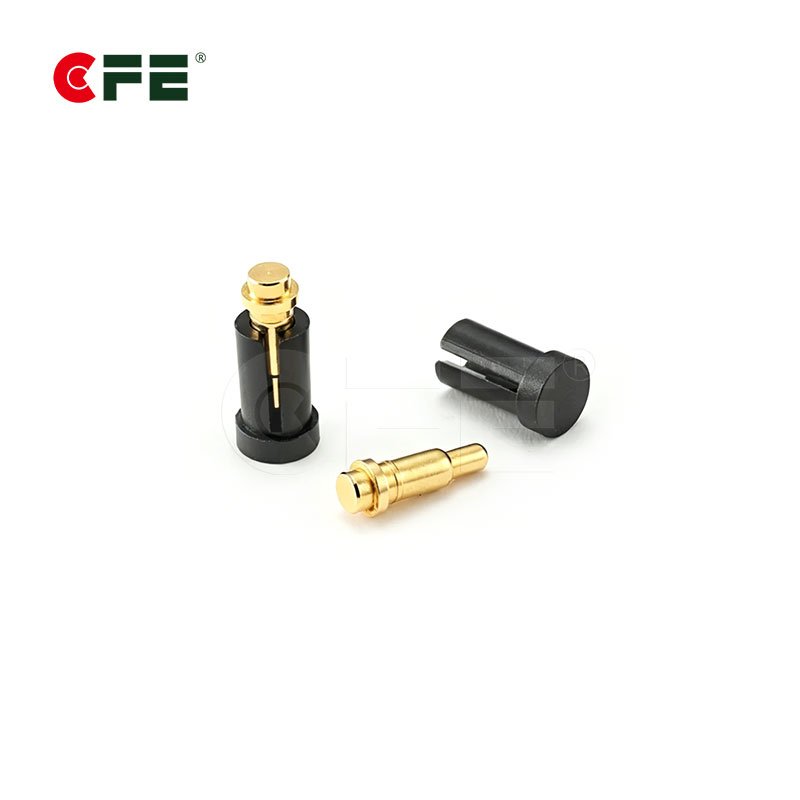
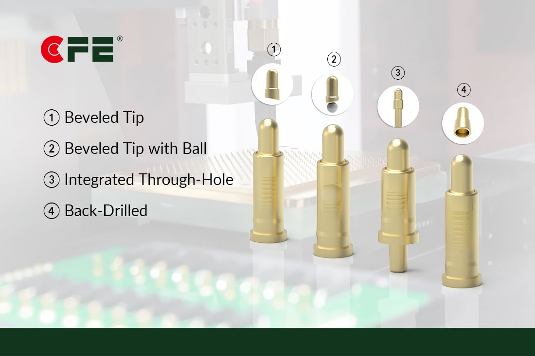
A pogo pin is a spring-loaded contact. A plunger slides inside a barrel, and a spring pushes the plunger tip against a mating pad. That design gives you a steady contact force even when parts shift, vibrate, or have loose tolerances.
The rating printed next to it, such as 5A, is not a promise that “this pin carries 5A.” It is a temperature statement. It means the pin stays at an acceptable temperature at that current, under defined conditions. CFE’s own guidance on waterproof pogo pins and magnetic connectors from 5A to 30A makes the same point: current rating depends on contact resistance, ambient heat, duty cycle, and the PCB and cable around the connector, not only on the pin.
Think of four people carrying a sofa. If all four lift together, the load is shared. If one lets go for a second, the other three suddenly carry more than they planned for. Pogo pins in parallel behave the same way, and the “letting go” can last a millisecond or the whole life of the product.
Reason 1: Current Never Splits Evenly
Electricity takes the easiest path. In a set of parallel pins, the pin with the lowest total resistance carries the most current. Total resistance includes the tip contact, the plunger-to-barrel interface, the spring path, and the solder joint at the tail. Every one of those varies slightly from pin to pin, and the tip contact varies the most. It depends on surface condition, plating wear, contact force, and how squarely the pin lands on the pad.

Here is the arithmetic. It uses 50 mΩ per pin, which is the maximum contact resistance CFE lists on the MXA-0010 5A magnetic connector datasheet. Treat it as a round number for illustration. Real values are usually lower, and the pattern holds either way.
| Scenario (20A total, four 5A pins) | Current per working pin | Heat per working pin (I² × 50 mΩ) | Versus design heat |
|---|---|---|---|
| All four pins make contact, perfectly even split | 5.0 A | 1.25 W | Baseline |
| One pin lifts or never touches | 6.7 A | 2.2 W | About 1.8 times higher |
| Two pins lift, for example from a tilted mating face | 10.0 A | 5.0 W | 4 times higher |
The first row is the best case, and you only reach it when everything is ideal. The other two are the cases that show up in returns and warranty claims. Your connector has no built-in way to tell you which row you are in.
Reason 2: Heat Grows With the Square of Current
The heat in any contact follows P = I² × R. Because current is squared, a small imbalance turns into a large heat problem. Push a pin from 5A to 6.7A and its current rises by a third, but its heat rises by nearly 80%. Push it to 10A and the heat quadruples.
That heat has to go somewhere. In a pogo pin it flows into a very small amount of brass, a thin spring, and a few square millimetres of PCB copper. Tight pin spacing makes it worse, because neighbouring pins warm each other, so each one runs hotter than it would alone. This is why a four-pin cluster cannot be treated as four independent heat sources.
Heat also does damage in stages. Warm plating wears faster. A hotter spring can lose force over time, which raises contact resistance, which raises heat again. Once that loop starts, the pin degrades a little with every cycle. Many “mystery” failures at 3 to 6 months in the field trace back to this loop rather than a sudden break. CFE’s breakdown of why pogo pins fail covers the other common causes alongside heat.
Reason 3: Mechanical Reality Beats the Drawing
On paper, four pins sit at the same height and land on four flat pads at the same moment. In a real assembly, nothing is perfectly flat or perfectly parallel. Pad heights differ. The mating part sits a fraction of a degree off. A housing flexes when a user presses the product into a dock. A connector that “seats” on the left side can leave the right-hand pin barely touching.
A pogo pin’s working stroke is short, often around a millimetre or two. Every tolerance that eats into that stroke weakens the contact force on one pin or another. Weaker force means higher resistance, and the current moves to its neighbours. If you want the numbers behind this, see CFE’s guides on pogo pin working height and what happens when a pin is over-compressed.

Magnets can help alignment, but they do not change the electrical rule. A magnetic connector pulls the halves together and fixes their position, yet the pins inside still have to share current, and the magnet force still has to beat the combined spring force with margin.
Reason 4: The Rest of the Path Sets the Limit Too
Even a perfect pin cluster cannot rescue a weak path around it. The same 20A has to travel through the solder joints, the PCB traces, the wires, and the mating pads on the other side. If any one of those is undersized, it becomes the hottest part of the product.
PCB copper is the usual culprit. How much current a trace can carry depends on its width, copper thickness, the allowed temperature rise, and whether heat can escape into planes or air. The industry reference for this is IPC-2152, which covers conductor sizing against current and temperature, including parallel conductors and power dissipation. A thin trace feeding four pogo pins can overheat long before the pins do.
Two quick checks save a lot of rework:
- Look at the mating pad. A 20A path needs generous copper and a clean, flat, well-plated pad on the other side.
- Look at the cable. Wire gauge, crimp quality, and solder terminals must all be rated for the full current, not just the connector.
Waterproof or Magnetic? The Problem Gets Harder
Add water protection and the margin shrinks again. Every seal that stops liquid also adds friction to the plunger, so spring force and stroke need to be planned around it. A sealed pin that has to carry real current gives the designer less room to “just add another pin.”
Wet contacts also corrode quickly when they are powered. If your design has exposed live pins, read CFE’s explanation of why powered pogo pin contacts corrode in water before you choose the pin count.


Magnetic connectors add one more trade-off. The MXA-0010 datasheet lists a 4.6 N magnetic force and a 120 g ±20% contact force at 1.0 mm working stroke per pin. Doubling the pins roughly doubles the spring push-back the magnets must overcome. A design that holds at two pins can drift open at four.
What a Real 20A Connection Looks Like
You have three sensible routes. Which one fits depends on your space, your life-cycle target, and how much risk you can accept.
| Approach | When it fits | Trade-off |
|---|---|---|
| One pin rated above your current, such as a 5A–30A high current pogo pin | Space allows a larger barrel, and you want the simplest path | Larger footprint and higher spring force |
| Two or three high-rating pins with deliberate derating | You need redundancy or a smaller pin diameter | Must be tested as an assembly, not assumed from datasheets |
| A custom connector built around your current, space, and mating face | Unusual shape, magnet needs, sealing, or tight cycle-life targets | Needs engineering time and sampling; see custom pogo pin connectors |
Notice what is missing from the table: “stack as many 5A pins as fit.” If your product genuinely needs several pins in parallel, the right question is not “how many pins add up to 20A” but “how much do I derate each pin, and what does the test data say about the whole assembly.” CFE’s customized module service exists for exactly that kind of system-level decision.
How to Specify a 20A Connector Before You Ask for a Quote
Most quoting delays come from missing information, not from complexity. Send this list together and the recommendation comes back faster and closer to final.
| What to send | Why it matters |
|---|---|
| Continuous and peak current | A 20A burst is a different job from 20A for hours |
| Voltage and whether pins are live while exposed | Sets corrosion risk and plating choice |
| Acceptable temperature rise and ambient range | Heat is the real limit, not the headline amp rating |
| Available space, pitch, and mounting style | Decides one large pin versus several smaller ones |
| Water and dust exposure | Decides the sealing method and how much force budget is left |
| Target mating cycles and product life | Guides plating thickness and spring design |
If you are comparing datasheets from different suppliers first, CFE’s guide on how to read a pogo pin connector datasheet walks through the ten specifications that matter most. If your connector must also carry signals, see whether pogo pins can carry power and data together.
Conclusion
Four 5A pogo pins give you four 5A contacts. They do not give you one 20A connection. Current shares unevenly, heat rises with the square of current, and tolerances decide which pins do the real work. The path around the pins, from PCB copper to cable, sets its own limit too.
The safer routes are a pin rated for the full current, or a deliberately derated design that has been tested as an assembly. Tell the engineering team your real current, duty cycle, space, and environment and they can recommend a part with margin. Request a quote and samples or email cfe@cfeconn.com.
Frequently Asked Questions
Can I use four 5A pogo pins in parallel for a 20A load?
Not safely, as a rule. The four pins will not share current equally, and if one touches late or lifts, the others carry more than 5A each. Use a pin rated for the full current, or derate heavily and validate the whole assembly with temperature testing.
How much should I derate parallel pogo pins?
There is no single number, because it depends on pin design, spacing, duty cycle, and mating tolerances. Choose a derating that keeps the worst-case pin, with one pin not touching, inside its rating, then confirm with a temperature-rise test. Ask the manufacturer for guidance on your specific part.
What limits the current rating of a pogo pin?
Temperature. Contact resistance, ambient heat, duty cycle, plating condition, and the PCB and cable around the pin all affect how hot it gets. The datasheet rating is a starting point, not a guarantee for your conditions.
Is a single high-current pogo pin better than several small ones?
For high current, usually yes, because one contact path removes the sharing problem. The trade-offs are a larger footprint and higher spring force. Where space is tight, a few high-rating pins with derating can work if tested as a set.
Does the same rule apply to magnetic connectors?
Yes. Magnets fix alignment but do not change how current splits between pins. A 5A magnetic connector is still a 5A connector, and adding pins also adds spring force the magnets must overcome.
Related reading: Waterproof Pogo Pin & Magnetic Connectors, 5A–30A