Picture two datasheets on your desk. Both list a pogo pin rated at 3A, and both look identical at a glance. One pin will run cool for years, and the other will quietly overheat inside your product. The difference is hiding in the fine print.
Datasheets are written by engineers, for engineers. If you are a buyer or a founder sourcing your first connector, they can feel like a wall of numbers. Here are the ten specifications that matter most, explained in plain English, with what to check before you trust each number.
A pogo pin connector datasheet is the manufacturer’s technical document listing a pin’s electrical ratings, mechanical dimensions, materials, and lifespan, along with the test conditions behind each figure. The test conditions matter as much as the numbers.

Current Rating
The current rating tells you how much current a single pin can carry. It is usually the first number people look at, and the one most often misread.
Current rating is the maximum current a pin can carry without exceeding a set temperature rise. Many manufacturers define it as the current that raises the pin’s temperature by about 30°C above ambient. Others quote a peak figure that is only safe for short bursts. Here is what to check:
- Continuous or peak: A 5A peak rating is not a 5A continuous rating. Look for the word “continuous” or a stated temperature rise.
- Per pin, not per connector: Neighbouring pins heat each other. Ask whether the rating assumes every pin is loaded at once.
- Ambient temperature: A rating measured at 25°C will not hold inside a sealed enclosure at 60°C.

If the datasheet does not say how the current rating was measured, treat it as a marketing number and ask the supplier for the test method.
Contact Resistance
Contact resistance is the electrical resistance where the pin meets its mating pad. Lower is better, because resistance turns into heat and voltage drop. It is typically listed in milliohms (mΩ), often as a maximum such as “50 mΩ or less.” Two details are easy to miss:
- Initial versus end-of-life: Contact resistance rises as a pin wears. A datasheet that shows only the initial value tells you half the story, so look for a figure after the rated number of cycles.
- Measurement conditions: Resistance depends on spring force, the mating surface, and the plating. A reading against a gold-plated pad will differ from one against bare copper.

In a charging application, extra milliohms mean lost power and a warm connector. On a signal line, they can mean unreliable data.
Spring Force and Working Stroke
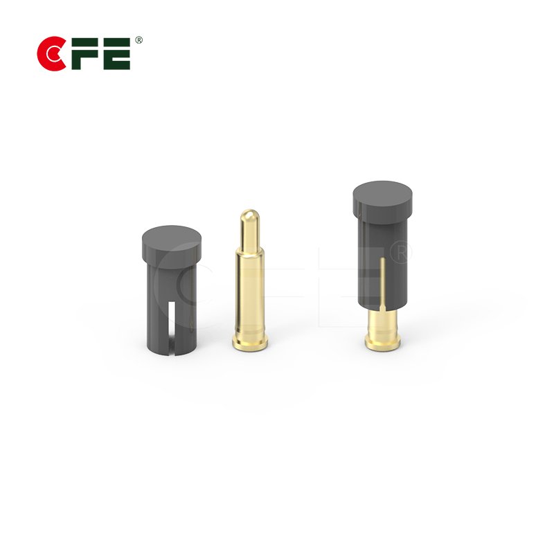
The “pogo” in pogo pin is the spring. Two specs describe how it behaves: spring force, meaning how hard the pin pushes back, and stroke, meaning how far the plunger can travel. Datasheets usually list several stroke figures:
- Free height: The pin’s length when uncompressed.
- Working height (working stroke): The compression where the pin is designed to operate. Force and resistance values are typically quoted here.
- Full stroke: The maximum compression before the pin bottoms out.

A common design mistake is running a pin at full stroke. It stresses the spring and shortens life. Aim for the working stroke and leave headroom for tolerance stack-up in your assembly.
Force is a trade-off. Higher force gives a more stable contact but makes mating harder and wears surfaces faster. Lower force is gentler but can lose contact under vibration.
Voltage Rating and Insulation
Voltage specs describe how much electrical stress the connector can handle. They are usually split into two figures:
- Rated voltage: The voltage the connector is designed to carry in normal use.
- Dielectric withstanding voltage: The higher voltage the housing can tolerate between pins without breaking down, usually for a set time.
- Insulation resistance: The resistance between adjacent pins through the housing material. It matters more in humid environments or with tightly spaced pins.

The key question is simple: does the rated voltage comfortably exceed what your product actually uses? Leave a safety margin, and if your product needs safety certification, check the connector’s ratings and creepage distances with your certification body rather than relying on the datasheet alone.
Pitch and Dimensions
Pitch is the center-to-center distance between adjacent pins. It determines how many pins fit in a given space, and it affects heat, voltage isolation, and alignment tolerance. Small connectors commonly run from about 1.0 mm to 2.54 mm, though options vary by manufacturer. Beyond pitch, scan the drawing for:
- Barrel and plunger diameter: These affect current capacity and the size of the mating pad.
- Overall length and mounting height: These decide whether the pin fits your enclosure.
- PCB footprint or mounting style: SMT, through-hole, and solder-cup terminations need different board layouts.
- Tolerances: A pitch of 2.0 mm ± 0.05 mm behaves very differently from ± 0.2 mm when you are aligning a mating part.
Tight pitch saves space but reduces margin for misalignment and heat, so compare the drawing to your mechanical design before ordering samples. For aligned mating designs, see our guide to magnetic connectors.
Plating and Materials
Plating is the thin metal coating on the pin’s surface. It decides how well the pin conducts, how long it resists corrosion, and how it holds up against wear. Most pogo pins use a gold finish over a nickel underlayer. The nickel acts as a barrier so the base metal does not migrate through the gold, and gold conducts well without oxidizing. Read these details closely:
- Gold thickness: Usually given in microinches or micrometers. A thicker layer generally lasts longer under repeated mating but costs more. A flash of gold can look the same as a proper layer on a datasheet, so look for an actual thickness figure.
- Base materials: Plungers and barrels are commonly brass or copper alloys, and springs are typically stainless steel or a spring-grade alloy. Ask which material is used for each part.
- Mating surface: The pad on the other side matters as much as the pin. Gold against gold is the safest pairing, while mixing metals can speed up wear or corrosion.
Mating Cycles
A mating cycle is one full connect and disconnect. The rated number of cycles tells you how long the connector should keep performing within spec. The number alone is nearly meaningless without its context, so check two things:
- Pass/fail criteria: What counts as end of life? A common definition is contact resistance rising above a set limit. If the datasheet does not say, the figure cannot be compared.
- Test conditions: Cycle tests with clean surfaces and perfect alignment are gentler than real use with dust, angled insertion, or vibration.
A useful reality check is to estimate how many times your product will actually mate. A device docked twice a day for five years sees roughly 3,650 cycles. Choose a rating with margin over your real need.
Operating Temperature
This spec states the range of ambient temperatures in which the connector can work reliably, usually shown as a minimum and maximum such as -40°C to 85°C. Keep two things in mind:
- It covers the whole assembly, not just the metal. The housing plastic, the spring, and any solder joints each have their own limits, and the weakest one sets the real range.
- Self-heating counts. A loaded pin runs hotter than its surroundings. If your enclosure already sits near the top of the range, current-driven heating can push the pin past its limit.

If you plan to use surface-mount pins in reflow, check whether the datasheet lists reflow temperature tolerance too. Some housings cannot survive standard lead-free profiles, an easy detail to miss until the first production run.
Housing Material and Termination Style
When a pogo pin connector has a housing, it holds the pins in position, insulates them from each other, and often defines how the connector mounts. Housing material affects heat tolerance, strength, and dimensional stability. The datasheet should name the material (nylon, PPS, and LCP are common) and, ideally, its flammability rating.
Termination style describes how the pin attaches to your circuit:
- SMT (surface mount): Fast to assemble and well suited to automated production.
- Through-hole (DIP): Stronger mechanical hold, useful where pins take side load.
- Solder cup or wire termination: Lets you connect a cable directly.
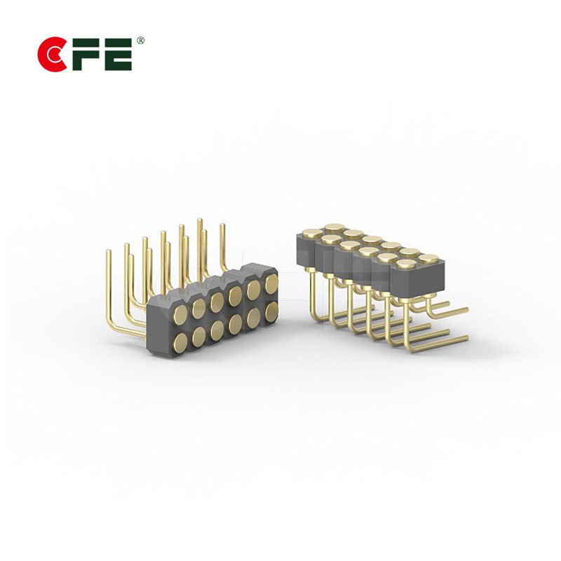
- Right-angle: Changes the mating direction relative to the board.
Termination choice affects assembly cost, board layout, and rework difficulty. Share your production process with the supplier early, or explore our custom pogo pin options.
Sealing and Compliance
The last category answers a practical question: can this connector survive where you are putting it, and can you legally sell it there? Ingress protection (IP) rating describes resistance to dust and water under the IEC 60529 system. Be careful here. A bare pogo pin is not sealed on its own, and many datasheets list an IP rating only for a specific assembled connector with gaskets or overmolding. Confirm what was tested. Also look for:
- Test standards: References to recognized methods, such as EIA-364 procedures for electrical connectors, show the numbers came from a defined process.
- Material compliance: RoHS and REACH statements matter if you sell in the EU and many other markets. The European Commission explains the RoHS directive on its site.

A datasheet that cites its test methods is a good sign. A datasheet with impressive numbers and no methods deserves a follow-up email.
Quick-Reference Summary Table
| Specification | What it tells you | Red flag to watch for |
|---|---|---|
| Current rating | Safe current per pin | No "continuous" label or temperature rise stated |
| Contact resistance | Efficiency and heat at the contact | Only an initial value, no end-of-life figure |
| Spring force and stroke | Contact stability and mating feel | Force quoted without the stroke it applies to |
| Voltage rating | Electrical safety margin | Rating barely above your operating voltage |
| Pitch and dimensions | Fit, heat, and alignment tolerance | Missing tolerances on the drawing |
| Plating and materials | Corrosion and wear resistance | No gold thickness figure |
| Mating cycles | Expected lifespan | No pass/fail criteria defined |
| Operating temperature | Safe ambient range | Ignores self-heating or reflow limits |
| Housing and termination | Mounting method and assembly cost | Housing material not named |
| Sealing and compliance | Environmental and legal readiness | IP rating with no test details |
Conclusion
A datasheet is a set of claims, and your job is to check how well each claim is supported. The ten specs above give engineers and buyers a framework for doing exactly that.
The short version: look past the headline numbers to the conditions behind them, match ratings to real use with margin, and ask for the test method whenever it is missing. Then request samples and verify the critical figures in your own assembly. If two datasheets look similar, trust the one that explains how its numbers were measured.
Frequently Asked Questions
What is the most important spec on a pogo pin datasheet?
It depends on your application. For power and charging, current rating and contact resistance matter most. For frequently mated fixtures, mating cycles and plating take priority. For compact wearables, pitch and dimensions often decide the design.
What does the current rating on a pogo pin mean?
It is the current a pin can carry before its temperature rises above a defined limit, often around 30°C above ambient. Confirm whether the number is continuous or peak, how it was measured, and whether it applies per pin.
How many mating cycles should a pogo pin be rated for?
Rate it well above your real need. Estimate how often the product will connect over its life, then add margin for misalignment, dust, and vibration. A device docked twice daily for five years sees about 3,650 cycles. Also check how the manufacturer defines end of life.
Why is gold plating used on pogo pins?
Gold conducts well and resists oxidation, so contact resistance stays low over long use. It is typically applied over a nickel underlayer, and thicker plating generally survives more mating cycles. Ask for the actual thickness.
Are pogo pin connectors waterproof?
Not by default. Waterproofing usually comes from gaskets, overmolding, or the enclosure design. When a datasheet lists an IP rating, confirm whether it applies to the pin alone or to a specific assembled connector.
Have a datasheet you are unsure about? Send it to the CFEConn team and we will walk through it with you, or browse our pogo pin connectors to compare options.