A connector rarely gets much attention in a design review. Then a prototype ships, the charging contact starts flickering after a few hundred docks, and that humble line on the bill of materials becomes the biggest risk on the project. Most of these problems trace back to a specification that skipped one or two basic questions.
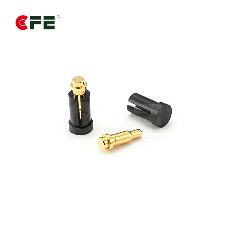
A pogo pin connector is a spring-loaded electrical contact, or a housing that holds several of them, that makes a connection by pressing against a mating pad instead of locking into a socket. If you want the fundamentals first, our guide to spring-loaded connectors vs. pogo pins covers the basics, and our pogo pin connectors page shows the full range.
The five questions below are the ones we would want answered before any drawing is released. Work through them in order and your shortlist usually shrinks to a handful of parts.
Quick answer: the 5 questions
- How much current and what kind of signal will it carry?
- How will it be mounted to your PCB?
- How many times will it mate, and in what environment?
- How much space and pitch do you have?
- Does a standard part fit, or do you need a custom design?
Question 1: How Much Current and What Kind of Signal Will It Carry?
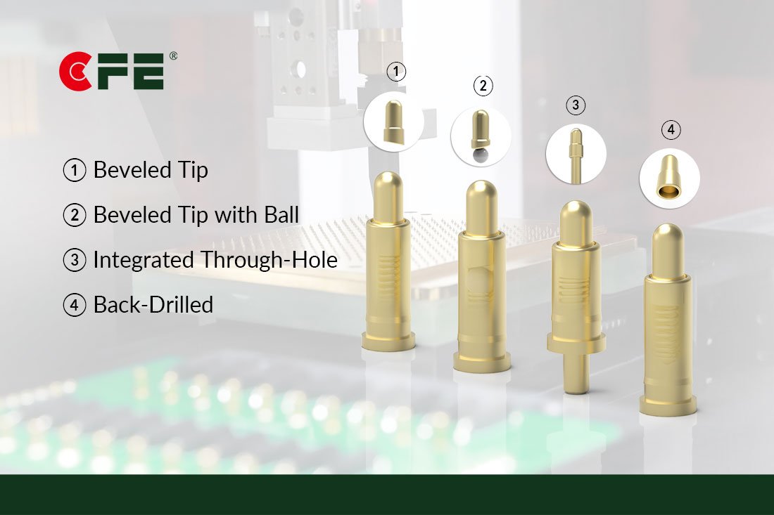
Current rating removes more options than any other filter, so start there. A pin that handles a 100 mA data line is a different part from one that has to deliver several amps of charging power. Pin diameter, plating, spring design, and the number of pins sharing the load all decide what is realistic.
Write down three numbers: continuous current per pin, peak current, and voltage. Then decide whether the pin carries power, data, or both. Power pins heat up as contact resistance rises, so a part that looks fine on the bench at low load can run warm inside a sealed enclosure. You can move up to a larger high-current pin, or spread the load across several pins in parallel. Be careful with the second option: parallel pins only share current evenly when every one of them touches reliably.
Data lines have the opposite worry. Low-voltage signals are sensitive to contact resistance and noise, so a stable gold-plated contact is the usual answer. For heavier charging and power work, our high-current pogo pin guide goes deeper.
Rule of thumb: size to the worst-case current at the highest ambient temperature your product will see, then leave margin. Ask for ratings quoted at a stated temperature rise, not just a headline figure.


Question 2: How Will It Be Mounted to Your PCB?
Mounting style decides how the connector goes onto your board. It also affects assembly cost, mechanical strength, and even how you can shape the product.
| Mounting style | Best suited for | Watch out for |
|---|---|---|
| SMT | Automated reflow lines and slim devices | Side loads need extra anchoring or support |
| DIP through-hole | Strong mechanical hold and board-to-board stacking | Added soldering step and taller profile |
| Solder cup | Wire-to-board links and flexible routing | Manual soldering of each wire |
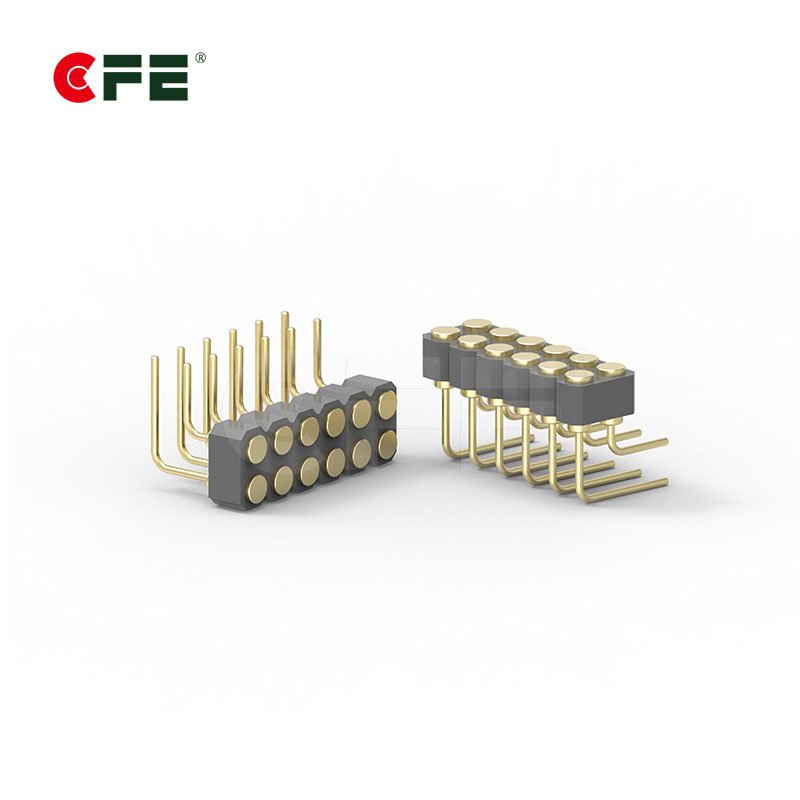
| Right angle | Contacts facing the board edge or the device side | Board-edge layout needs planning early |
If your line already runs reflow, SMT is usually the path of least resistance. If the connector will take knocks, such as a dock someone pulls a device from dozens of times a week, through-hole anchoring is more forgiving. Right-angle versions are the answer when the mating surface sits on the side of the device. Solder cup suits cases where the pin lives on a small sub-board and wires run back to the main PCB. For a deeper comparison with conventional connectors, see pogo pins vs. traditional board-to-board headers.


Question 3: How Many Times Will It Mate, and in What Environment?
Datasheets list mating cycles, but products live in pockets, gyms, kitchens, and vehicles. Do the arithmetic for your own use case. A wearable docked twice a day for three years sees roughly 2,200 cycles. A payment terminal returned to its cradle all day in a busy shop can reach tens of thousands. Multiply, then add margin.
Environment is the second half of the answer. Sweat, salt, humidity, and cleaning chemicals all attack contacts, and plating is your main defense. Gold over a suitable base layer gives low resistance and good corrosion resistance, which is why it is common on consumer devices. Vibration matters too, especially in robotics and vehicles, where a weak spring can lose contact for a split second.
If the product needs to be water-resistant, be specific. An IP rating, defined under the IEC’s ingress protection system, describes how a finished product performs in testing, not how a bare pin behaves. So ask how the connector area is sealed, whether through gaskets, housing design, or potting, and test the assembled unit.


Question 4: How Much Space and Pitch Do You Have?
Pitch is the distance between pin centers. A smaller pitch saves room, but it tightens tolerances on alignment, spring travel, and pad size. On the mating side, make the contact pads larger than the pin tips so a slightly off-center dock still connects.
Also check compression height. In the final assembly the pin should sit inside its working stroke, neither bottomed out nor barely touching. Tolerance stack-up across the housing, the PCB, and the mating part is where this usually goes wrong, so add it to your design review.
Compact devices like earbuds and rings make these limits obvious. Our article on pogo pin connectors in TWS earbuds and wearables shows how small designs handle them. If you are weighing a different approach, the comparison of magnetic vs. pogo pin connectors explains where each one fits.


Question 5: Does a Standard Part Fit, or Do You Need a Custom Design?
Check the catalog first. A standard part is faster to source, easier to second-source, and already proven. Go custom when your pin count, pitch, housing shape, spring force, or plating falls outside what is on the shelf. Custom work brings tooling and lead time, so decide early rather than after the enclosure is frozen.
Compliance belongs in this conversation too. If you sell into the EU and other regulated markets, ask for RoHS and REACH documentation up front, along with the supplier’s quality management certificates. Then order samples and test them under your real conditions: your dock, your cycle count, your temperature. Bench results from a datasheet only go so far.


Your Pre-Specification Checklist at a Glance
| Question | What to define | Typical decision |
|---|---|---|
| 1. Current and signal | Continuous and peak current, voltage, power vs. data | Pin size, plating, number of pins |
| 2. Mounting | Assembly process and mechanical load | SMT, DIP, solder cup, or right angle |
| 3. Cycles and environment | Docking frequency, moisture, vibration | Plating, spring design, sealing approach |
| 4. Space and pitch | Footprint, stroke, tolerance stack | Pitch, pin height, pad size |
| 5. Standard or custom | Gaps in the catalog, compliance needs | Catalog part or custom design |
Conclusion
Specifying a pogo pin connector comes down to five practical questions: what it carries, how it mounts, how often and where it mates, how much room it has, and whether a standard part will do. Answer them honestly and most of the risk disappears before the first sample arrives. Browse our full range of pogo pin connectors, or talk to the CFE team with your current, pitch, and cycle requirements and we will help you narrow the options.
Frequently Asked Questions
What should I check first when choosing a pogo pin connector?
Start with current and signal type. Current rating eliminates more options than any other factor, and it influences pin size, plating, and how many pins you need.
Which mounting style is best for pogo pin connectors?
It depends on your assembly process and mechanical load. SMT suits automated reflow and slim devices, DIP through-hole gives stronger retention, solder cup suits wire connections, and right angle suits side-facing contacts.
How do I estimate the mating cycles I need?
Multiply expected uses per day by days per year and by product lifetime, then add margin. A wearable docked twice daily for three years sees about 2,200 cycles, while shared or commercial devices can see far more.
Can pogo pin connectors be waterproof?
They can be part of a water-resistant design when the connector area is sealed properly. IP ratings apply to the finished product, so confirm the sealing method and test the complete assembly.
When should I choose a custom pogo pin connector?
Choose custom when pin count, pitch, housing shape, spring force, or plating cannot be met by a standard part. Raise it early, because tooling and lead time affect your schedule.