Pogo pins fail for a short list of repeatable reasons: contaminated contact surfaces, worn plating, fatigued springs, misalignment, excess current, and poor assembly. Every one of them is preventable, and most give warning signs long before a device stops working.
If you have ever chased an intermittent charging fault, or a test fixture that passed on Monday and failed on Thursday, you know how slippery these problems are. A spring-loaded contact rarely breaks outright. It drifts, and the drift gets blamed on firmware, cables, or batteries first. This guide covers what actually goes wrong inside a pogo pin and what to change to stop it. If you are still choosing a contact, CFE’s range of pogo pin connectors is a useful place to compare styles as you read.
What Is a Pogo Pin, and What Does Failure Actually Mean?
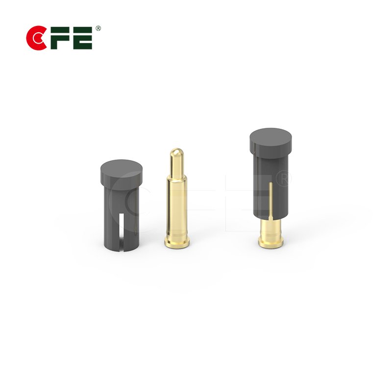
A pogo pin is a spring-loaded electrical contact made of a plunger, a barrel, and a spring. The spring pushes the plunger against a mating pad, which keeps the connection steady even when the two parts shift slightly.

You will find them in charging docks, wearables, payment terminals, test fixtures, and robotics. The name is a registered trademark of Everett Charles Technologies, according to Wikipedia’s entry on the pogo pin, though most people use it generically. Designers like these contacts because they tolerate small misalignments, survive repeated mating, and take far less room than a conventional connector.
“Failure” is a slippery word here. In practice it appears in three forms:
- Electrical failure: contact resistance climbs, or the connection drops out intermittently.
- Mechanical failure: the plunger sticks, the spring loses force, or the barrel deforms.
- Environmental failure: corrosion or contamination degrades the contact surface.
These feed each other. Corrosion raises resistance, resistance creates heat, and heat weakens the spring. Prevention is a matter of choosing which link to break first.
Contamination and Oxidation on the Contact Surface
One of the most frequent culprits is also the least dramatic: dirt. A film of skin oil, flux residue, or lint on the tip is enough to cause trouble, because a pogo pin has a small contact area and a modest spring force. It cannot scrape through an insulating layer the way a larger connector sometimes can.

The physics is well documented. ASTM’s test method for measuring connection resistance explains that contact resistance has two parts, constriction resistance and film resistance, and that a film, when present, usually dominates the total. A clean metal-to-metal touch gives the lowest resistance, and anything between the surfaces makes it worse.
Typical contaminants:
- Skin oils and sweat (sweat carries corrosive salts)
- Flux residue and adhesive vapor from assembly
- Dust, fibers, and metal particles
- Sulfur-bearing air, which tarnishes silver quickly
How to prevent it: choose a noble plating such as gold for long-life products, recess or shield the pins in the housing, keep flux away from contact faces during assembly, and add a cleaning step to maintenance. A lint-free swab with a little isopropyl alcohol handles most routine contamination.
Plating Wear and Corrosion
Plating is the pin’s skin, and it takes a beating. A common build uses a brass or copper-alloy base, a nickel underlayer, and a gold finish. The nickel acts as a barrier so base metal cannot creep to the surface, and the gold provides low resistance and corrosion resistance.

The catch is that gold is thin. Every mating cycle abrades it a little, and once it wears through to the nickel, oxidation starts quickly. Nickel oxide is a poor conductor. Trouble usually traces back to one of these:
- Thin gold for the required cycle life, or soft gold where an alloyed, harder gold was needed
- Porosity, which lets moisture reach the base metal
- Galvanic mismatch between pin and pad in the presence of moisture
- Fretting corrosion, where tiny vibrations grind the surface and create insulating debris
| Plating choice | Strength | Weakness | Suits |
|---|---|---|---|
| Hard gold over nickel | Low resistance, good wear life | Higher cost | Long-life wearables, medical, low-signal circuits |
| Thin flash gold | Low cost, good initial contact | Wears through quickly | Low-cycle, short-life products |
| Silver | Excellent conductivity | Tarnishes, especially around sulfur | Dry, controlled environments |
| Rhodium or ruthenium | Very hard and durable | Cost, and resistance can be higher | High-cycle test fixtures |
How to prevent it: match plating thickness and hardness to your real mating-cycle target, and use compatible plating on the pin and its pad. Salt spray testing under ASTM B117 is a handy way to compare coatings, but the standard itself cautions that results seldom correlate with natural environments as stand-alone data. Use it for ranking, then back it up with tests that resemble real use.
Spring Fatigue and Cycle Life Limits
Inside every pogo pin is a small spring, and springs get tired. Each compression stresses the metal, and over time the spring can lose force, an effect known as set or stress relaxation. Less force means less contact pressure, which means higher resistance and a weaker connection.

Rated cycle life varies enormously between designs, and any catalogue figure comes from specific test conditions. Add current, heat, or side load, and real-world life usually comes in lower. What speeds up spring fatigue:
- Over-compression: running near full stroke every cycle is like bending a paperclip to its limit each time.
- Heat: current warms the spring, and higher temperature accelerates relaxation.
- The wrong spring material: music wire, stainless steel, and copper alloys behave differently under heat and corrosion.
- High duty cycles: a fixture cycling all shift ages a pin far faster than a dock used twice a day.
How to prevent it: keep the pin working comfortably inside its travel rather than at the extremes, and confirm the recommended working stroke on the datasheet. Ask your supplier for cycle-life data under conditions like yours, and after life testing, measure spring force as well as continuity. A pin that still conducts but has lost much of its force is a failure waiting to happen.
Misalignment and Side Loading
Pogo pins are built to compress along their axis. Push them sideways and things go wrong quickly. An angled plunger presses hard against one wall of the barrel, which creates friction, uneven wear, and eventually a plunger that binds. A stuck plunger means no spring action, so the contact turns erratic or dead.

Misalignment usually sneaks in through the mechanical design rather than the pin itself:
- Loose tolerances between the mating parts
- A housing that flexes when handled
- Docking features that let the device rock or twist
- Pads too small for the pin’s positional tolerance
Think of a door hinge: one hung a few degrees crooked wears out and eventually stops closing. Moving equipment adds vibration, which invites the fretting corrosion mentioned earlier.
How to prevent it: add guides, magnets, or alignment pins so the parts land where they should, and size mating pads generously to absorb tolerance stack-up. Then test with deliberate misalignment, because real users are not gentle.
Overcurrent and Heat Damage
A pogo pin’s small contact area limits how much current it can carry safely. Heat generated in a contact follows the familiar relationship of power equals current squared times resistance, so doubling the current quadruples the heating. That is why fast-charging designs are so demanding on contacts.

Hot contacts oxidize faster, soften springs, and can deform plastic housings. Signs of thermal trouble include a discolored plunger tip, a slight burnt smell, a warped housing, or a connector that feels warm in use.
How to design around it:
- Derate the current. Do not run pins at their published maximum, especially when ambient temperature is high.
- Use pins in parallel for power lines, but do not assume they share current equally. Small resistance differences can push more current through one pin.
- Choose a pin rated for the load. Larger, high current designs exist for exactly this reason.
- Keep contact resistance low with good plating, adequate spring force, and clean surfaces.
Poor Mounting, Soldering, and Assembly
Sometimes the pin is fine and the way it was installed is the problem. Surface-mount and through-hole pins both depend on solid solder joints, because every compression sends force straight into that joint. If coverage is weak, the pin can loosen, tilt, or even lift its pad off the board.

Assembly mistakes that cause trouble:
- Flux wicking up the barrel and gumming the plunger
- Too much heat during soldering, which can damage the spring
- Solder wicking into the barrel, which locks the mechanism
- Uneven pin height across an array, leaving some pins barely compressed
Height uniformity matters most in multi-pin arrays. One pin sitting slightly lower than its neighbors may not touch reliably, and you get an intermittent fault that only appears at a certain angle.
How to prevent it: use a controlled soldering profile, choose pins designed for your process, and inspect arrays for coplanarity. Validate a first-article build with a full electrical and mechanical check before scaling up.
Early Warning Signs Before a Pogo Pin Fails
Catching a problem early saves days of troubleshooting. Watch for these symptoms:
- An intermittent connection that improves when you wiggle the device
- Contact resistance creeping upward in test logs
- Slow or interrupted charging
- Dark spots, green residue, or scratches on the tip
- A plunger that feels gritty or does not spring back promptly
If you have a test setup, log contact resistance over time. A steady upward trend is a better early warning than a single pass-or-fail reading, and it echoes the before-and-after-life-test comparison ASTM B539 describes for judging contact stability.
A Practical Prevention Checklist
Before you commit to a pogo pin design, walk through this list:
- Define the requirements honestly: current, voltage, mating cycles, environment, and user behavior.
- Select plating and materials to match, including the mating surface.
- Set the working travel inside the pin’s stroke, with tolerance headroom.
- Design alignment features so the housing absorbs misalignment, not the pin.
- Derate current and plan a thermal path.
- Control assembly: soldering profile, flux, and coplanarity.
- Test realistically: life cycling, vibration, humidity, sweat or salt exposure, and misalignment.
- Plan maintenance and cleaning if the contacts will face dirt.
Choosing a Pin Style That Matches Your Failure Risks
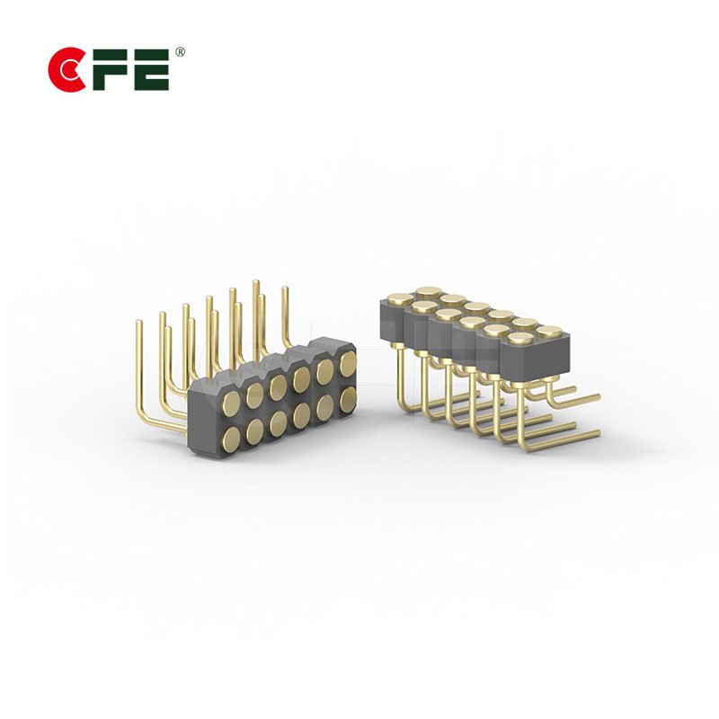
Many failures are really style mismatches. CFE, which has built pogo pin and magnetic connection solutions since 2009, lists SMT, DIP, right angle, double-ended, solder cup, and thread types, plus high current and waterproof options (up to IPX8 on its product pages).


SMT pins suit low-profile boards but demand coplanarity control. DIP pins anchor mechanically through the board, which helps under repeated mating force. When no standard style meets your current, sealing, or footprint needs, a custom design is often cheaper than fighting a poor fit in the field. Browse the options on CFE’s pogo pin connector page.
Conclusion
Pogo pins rarely fail for mysterious reasons. The usual suspects are contamination, worn plating, tired springs, misalignment, overheating, and assembly mistakes, and they tend to reinforce one another. Almost every one can be prevented with sensible design choices and honest testing.
If you take one idea away, make it this: design for the messy reality of use, not the clean conditions of a datasheet, and verify the pin with tests that look like real life.

Not sure which pin fits your design? Share your current, cycle, and environment requirements with CFE’s engineers and get a recommendation that matches your application.
Frequently Asked Questions
What is the most common reason pogo pins fail?
Contamination and oxidation on the contact surface are among the most frequent causes. With a small contact area and limited wiping action, even a thin film of oil, dust, or flux can raise resistance or cause intermittent connections. Clean assembly, protective housings, and routine cleaning reduce the risk.
How many cycles should a pogo pin last?
It depends on the design, plating, spring, and operating conditions. Ratings vary widely between cost-optimized pins and premium test-grade contacts, and catalogue values assume controlled conditions. Ask your supplier for test data that matches your application.
Can I clean a pogo pin, and how?
Yes. Power the device down, then gently wipe the tips with a lint-free swab lightly dampened with isopropyl alcohol. Avoid abrasives that strip plating, and do not flood the pin. If the plunger still sticks afterward, replace it.
Why do my pogo pins get hot?
Heat comes from current passing through contact resistance. Dirt, worn plating, and weak spring force raise that resistance, and running near the maximum rating makes it worse. Reduce the load, add parallel pins, or move to a pin rated for higher current.
How can I prevent misalignment problems?
Add guides, magnets, or alignment pins so the mating parts self-center, make the mating pads larger than the pin’s positional tolerance, and test with intentional misalignment during validation.